sinned6915
New member
- Joined
- Dec 30, 2012
- Messages
- 2
Greetings all-
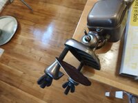
I am trying to re-assemble a Dazor P-2134 that I got in pieces, less the ballasts (I was told it only needed ballasts, but I question that advice now). One of the lamp sockets has been replaced and the wiring in the upper part of the lamp has been 'adultered'. I think I have it figured out, but would appreciate extra eyes on it before I let out any blue magic smoke from the genie bottle.
Taking apart a known good P-2134 I have, it only has 3 wires coming to the base- a Black, Brown and Yellow. This lamp only uses 6 pins on the switch. It pretty much matches what @Bert_ drew up in this thread with the exception that the Black 'OFF' switch is on the Neutral leg, not the inputs for the ballasts.
 www.garagejournal.com
My known good lamp schematic:

The unknown lamp's schematic:

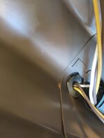
I cannot for the life of me get the schematic based on my pinning of the wires to make any sense assuming the wires to the base all need to be connected. I have 4 wires coming out at the base of the light from the lamps/switch. It uses all 8 pins on the switch.
I am thinking that I should cap the Yellow wire in the base and leave the rest alone, using the Red wire as a Line and the Yellow#1/Red wire at switch terminal joint as a connection. Then the rest makes sense.
Can anyone comment and/or confirm ?
Dennis
I am trying to re-assemble a Dazor P-2134 that I got in pieces, less the ballasts (I was told it only needed ballasts, but I question that advice now). One of the lamp sockets has been replaced and the wiring in the upper part of the lamp has been 'adultered'. I think I have it figured out, but would appreciate extra eyes on it before I let out any blue magic smoke from the genie bottle.
Taking apart a known good P-2134 I have, it only has 3 wires coming to the base- a Black, Brown and Yellow. This lamp only uses 6 pins on the switch. It pretty much matches what @Bert_ drew up in this thread with the exception that the Black 'OFF' switch is on the Neutral leg, not the inputs for the ballasts.
Dazor 2134 lamp only one bulb works
It's often called a draftsman lamp. It has two 18" fluorescent tubes. It's not the bulbs. I swapped in multiple new bulbs at the hardware store and only one will come on at a time. It's not specific to one side or the other. Sometimes one side comes on, sometimes the other side comes on, but...
www.garagejournal.com
My known good lamp schematic:
The unknown lamp's schematic:
I cannot for the life of me get the schematic based on my pinning of the wires to make any sense assuming the wires to the base all need to be connected. I have 4 wires coming out at the base of the light from the lamps/switch. It uses all 8 pins on the switch.
Brown to the base from the upper lamp checks.
White to the base from the upper lamp checks.
White to the base from the upper lamp checks.
Red to the base makes no sense
Yellow to the base makes no sense
If the Red 'START' switch is depressed, then the Red and Yellow#1 wire will connect to the Yellow wire going to the base. That means that the Red and Yellow would short if connected to Line or Neutral. I am thinking that I should cap the Yellow wire in the base and leave the rest alone, using the Red wire as a Line and the Yellow#1/Red wire at switch terminal joint as a connection. Then the rest makes sense.
Can anyone comment and/or confirm ?
Dennis