To avoid these ads, REGISTER NOW!

Delta 17" Drill Press Restoration With VFD

MBeaty

Well-known member
Joined
Feb 1, 2010
Messages
237
Location
Middle Tennessee
Ever since graduating from college I have been the proud owner of a free to me bench top Atlas drill press from the 40's or early 50's. I never figured out exactly what it was, but had it narrowed down to a model 62,63, or 64. I built many great projects with this drill press, routinely pushing it past its limits drilling 3/8" holes in steel, asking every bit from the 1/3 HP motor and belts. I knew that this continued abuse would be detrimental to the drill press, so I began to look for something slightly larger and with more speed control. The old Atlas drill press I had was only a 4 sped drill press and was definitely designed with woodwork in mind.

Old%20Drill%20Press.JPG


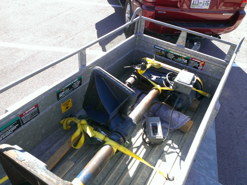
After a long search on Craigslist I finally found an older delta 17" drill press for sale at a reasonable price. I quickly made the 1.5 hour trip to go and take a look at it. Overall it was in decent mechanical condition, but looked really poor due to a terrible paint job. Also, it was wired up for 480V with the original 3 phase motor.

The old Atlas 15" drill press was heavy for its size, but could still be picked up when needed, but this 17" Delta was far more massive and quite difficult to move due to all the weight being at the very top and bottom.

Ride%20Home.jpg


The previous owner had intentions to restore this drill press, but it had been sitting around for several years and was just taking up space.

Size%20Comparison.jpg


This picture really puts the size difference into perspective.

I did not mind the 3 phase motor because I was planning on adding a new 3 phase motor and VFD to the drill press. This particular drill press had the more common woodworking speed range, but had 5 speeds, so it would not take too much turn down from the VFD in order to get the speeds slow enough for good drill bit life in steel.

The%20Table.JPG


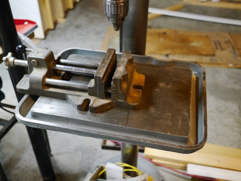
Another very desirable feature of this drill press was the large "production" table with minimal signs of an arc of shame.

Awful%20Paint.JPG


Here is a good picture showing how appalling the previous paint job was. In fact the last several paint jobs were terrible, but the blue paint had to have been brushed on with absolutely no prep work. Most of the texture on the pain was actually metal chips and shavings that were merely pained over! While this looked terrible, I knew that I had plants to disassemble and repaint the entire drill press anyway, so it was not too bothersome to me.

The plan was to restore the entire drill press adding a 3/4 to 1 HP three phase motor and a VFD to gain better speed control. My end goal was to make a very functional drill press that could comfortably drill 1/2" diameter holes in steel with the possibility to drill some 3/4" holes in rare occasions.

My day job is a mechanical engineer, so I knew that I was going to be drifting slightly out of my comfort zone with the VFD, but I am always up for a good challenge. Most of this project is actually complete, but I will update this as I have time to document the work that I already completed.
 
Last edited:
To avoid these ads, REGISTER NOW!

zkling

Well-known member
Joined
Jan 23, 2007
Messages
16,939
Nice machines. The Delta 17" are a good medium size machine. I'd certainty keep the atlas if I was you. The production tables IMHO are more of a hindrance than anything on a general press. Why do you want to drop the original motor?
 

Boxerrider

Member
Joined
Apr 8, 2015
Messages
18
Location
Central Texas
Nice machines. The Delta 17" are a good medium size machine. I'd certainty keep the atlas if I was you. The production tables IMHO are more of a hindrance than anything on a general press. Why do you want to drop the original motor?

Have you thoroughly verified that the motor isn't dual-voltage? My 17" Delta has its original 1hp, 3ph motor wired 220V from a VFD. Great set-up!

Jeff
 
OP
M

MBeaty

Well-known member
Joined
Feb 1, 2010
Messages
237
Location
Middle Tennessee
The production tables IMHO are more of a hindrance than anything on a general press. Why do you want to drop the original motor?

Have you thoroughly verified that the motor isn't dual-voltage? My 17" Delta has its original 1hp, 3ph motor wired 220V from a VFD. Great set-up!

I agree that under some condition like trying to clamp a small part down, the production table can be a hassle with the deep coolant and shaving thought around the perimeter and large cast iron webs underneath. My reasoning for wanting a large table was to support my drill press vise. I found a great deal on an older Heinrich SV-6 on ebay not realizing how much larger this 6" vise was than the typical import drill press vise.

Here is the production table with the SV-6 on it. Without rotating the table to the side, the end of the vise hangs off the table.

Vise%20on%20Table.JPG


Needless to say this vise was barely functional on the 15" Atlas.

With regards to the motor, I had several reasons why I wanted to change. The first reason was for better low speed control. I knew I wanted to target somewhere around a 300 RPM spindle speed with minimal turn down on the VFD. After measuring the stock pulleys I came up with the following speed chart.

Speed%20Chart.bmp


As you can see with the stock 1800 RPM motor, at 60 Hz the spindle would have been about twice as fast as I was wanting. I know that a modern motor designed for inverter duty, should be well within its full torque operating range at a 2:1 turn down, but I was not too sure about the stock motor after having 40 years of use on it. I was somewhat afraid that I was going to burn through the insulation on the windings.

I wanted to put a 900 or 1200 RPM motor on it, but ended up settling on 1200 RPM due to availability. As you can see in the chart, with only 20% turndown to a motor speed of 840 RPM, I would be right at the target speed.

The stock motor was a dual voltage motor. In hindsight it probably would have held up for quite some time due to me using a VFD with a 240v output. Even with voltage spikes it probably would have still been under 480v.

The last reason for changing the motor was simply finding a good deal on a combo including the new motor and VFD.

I still have the stock double shaft motor if anyone knows of someone who needs it. I am sure it would be valuable to someone wanting to restore a vintage Delta/Rockwell machine. Shipping would be pretty brutal on it though!
 

zkling

Well-known member
Joined
Jan 23, 2007
Messages
16,939
If you are set on getting a new motor too, go with a DC drive system from the ground up.

I almost purchased a Heinrich 8" vise till I measured it in person, too big for the 17" delta. A 4 or 6" would be perfect for that machine though.
 
OP
M

MBeaty

Well-known member
Joined
Feb 1, 2010
Messages
237
Location
Middle Tennessee
Thanks to OWWM, it was very easy to come by several versions of the manuals for this style of drill press complete with nice exploded views of the major components.

I started the disassemble with the head unit of the drill press, stripping each part off to get it down to bare castings.

Head%20Unit.JPG


Between the several coats of paint, I used a combination of electrolysis, a wire brush wheel, and paint stripper on few parts. It sure was messy to remove, but I am glad there was bad paint rather than bad rust! I wish I had taken a picture, but the belt cover actually had 5 layers of paint, all of a different colors.

So%20Much%20Paint.JPG


Electrolysis%20Bath.JPG


If you go through the effort of electrolysis, do yourself a favor and buy some un-plated carbon arch gouge electrodes to use rather than scrap steel. It keeps the bath so clean that it can be reused time and time again.

The head unit was actually quite easy to disassemble. I was expecting the quill return spring to be a pain, but due to a very clever design it was quite uneventful, but more on this later.

During the disassemble of the table crank gearbox, several fiber type washers fell broke off from the crank assembly. These washers reduced the slop in the gearbox as well as reduced the friction. The crank lever worked effortlessly while the table was going down, but on the way up was pretty tight due to the weight of the production table.

Table%20Crank.bmp


This drawing shows the rough design. SP-683 was really several parts that acted as a thrust bearing. In looking for replacement washers online, I noticed that McMaster Carr had real thrust bearings for less than I was going to pay for the fiber washers.

Thrust%20Bearing%20Modification.JPG


The fiber washers would have gone between the two collars on the shaft. The thrust bearing and ground washer are in front.

Thrust%20Bearing%20Assembly.JPG


The completed assembly with a brass spacer and two thrust bearings. This removed nearly all of the slop from the gearbox and made the action much smoother.

Once all of the castings were cleaned off, I brush painted them using Rustoleum smoke grey enamel thinned with Penetrol. Most of the cast surfaces had surface texture to the casting, so the painting was quite easy, but overall I was pleased with how smooth the finish was for being brushed.

Paint%20Finish.JPG


While I had the head unit apart and was waiting for paint to dry I went ahead and replaced all four bearings on the spindle and quill. Most of them were pretty affordable and easy to come by, but the top bearing above the spindle pulley was a little more rare. It had a snap ring groove in it to hold the bearing in location and ended up costing around $20.

Spindle%20Bearings.JPG


These are the two spindle bearings. The snap ring can be seen on the upper bearing.

The top bearing with the snap ring is a New Departure C487503
The lower spindle bearing is a New Departure 88503

The two bearings in the quill assembly are both MRC 203.

While I was happy with the paint finish, I was amazed how long the Rustoleum took to dry. to the point where parts could be reassembled. Eventually after about 4 or 5 days I was able to gently work on the painted parts without damaging the paint.

Much%20Nicer%20Looking%20Now.JPG


Comparing this picture to the one at the top of this post, it is amazing what a little elbow grease and paint can do!

Also in this picture, you can clearly see the clever design that I mentioned earlier. The quill return spring housing had threads cut around the OD. This mated with a screw that went through the head casting which allowed the whole assembly to be put together with no spring tension and easily wound afterwards.

The worst damage that I found was a bent tooth on the quill down feed pinion.

Bent%20Tooth.JPG


This did not prevent the drill press from functioning, but it did cause the quill to hang up while it was trying to self retract. A small amount of work with a needle file easily corrected it to the point where it was no longer noticeable while moving the quill up and down.
 

RickP

Well-known member
Joined
Jan 15, 2013
Messages
1,549
Location
Annapolis, MD
Nice paint job - and your elbow grease on all those old layers of paint really makes it look good. Very cool design for the spring tensioner.
 
To avoid these ads, REGISTER NOW!
OP
M

MBeaty

Well-known member
Joined
Feb 1, 2010
Messages
237
Location
Middle Tennessee
I did the same resto project with VFD as you a couple years ago on an identical DP.
Check out post, #20 in link.

http://www.garagejournal.com/forum/showthread.php?t=240309&highlight=svtride

Very nice work there! That is almost the exact same combo I went for with the Teco drive.

Look forward to your write up.
Good luck.

Looking great!

Very fun. Looks great.

Nice paint job - and your elbow grease on all those old layers of paint really makes it look good. Very cool design for the spring tensioner.

Thanks!
 
OP
M

MBeaty

Well-known member
Joined
Feb 1, 2010
Messages
237
Location
Middle Tennessee
With all the cleanup and painting done, the real assembly and fabrication work for the VFD mods could be started.

I bought a Teco Westinghouse JNEV-101-H1 vfd and a Brooks Crompton FA6N.75-2 Motor.

The VFD is rated for 1 HP max with 120v single phase in and 240 three phase output.

The motor nameplate 3/4 HP and 1130 rpm. This motor was designed with inverters in mind, so the cooling fan is designed for effective cooling at lower frequencies, so hopefully it should hold up well over the long haul. The motor also features a 5:1 constant torque rating and 10:1 variable torque rating. This was all new to me when I was looking at inverter duty motors, but basically it means that this motor will will have a constant torque over a ratio of 5:1 of the input hz. This means in my application I will have the full rated torque from 60 hz down to 12 hz, which equates to roughly 75 RPM spindle speed on the lowest pulley ratio.

While this is possible in theory, I doubt the standard A type V belt will be very effective at this low of speed without really high belt tension.

Since this was all new to me, I decided to hook up the VFD and motor for a dry run to play with settings and parameters prior to mounting it on the drill press.

Test%20Run.jpg


Everything worked great, as long as it was not hooked up through an outlet with a GFCI. Each time I would start the motor, the GFCI would trip. From some research it seems like this is a common problem with very few reasonable solutions for "home use." All of the wiring was simple 12g copper wire, but for the final installation I had some nice 3 conductor shielded VFD cable, which I had hoped would solve the GFCI problem.

The VFD measures roughly 5" tall x 5" deep x 3" wide. Based off manufacturer recommendations, for effective cooling of the VFD, the enclusure should be 4 times the volume of the drive, assuming it is a metal enclosure.

5x5x3 = 75in^3 for the drive
75in^3 x 4 = 300 in^3 minimum volume for the junction box (roughly 8"x8"x4")

In most cases it would be tough to mount the VFD in a box smaller than this ratio and have room for the terminations. I chose a 12"x12"x6," which should leave plenty of room for remote mounted controls as well as a breaker and terminal strip for future additions like a work light.

I did not want to drill any holes in the drill press head casting to mount the electrical box, so I designed a clamp and frame that would attach to the drill press column and would support the electrical box.

JB%20Frame%20Clamp.JPG


I started by cutting some 1/2" steel plate into the two halves of the clamp. This was quite tedious work with a jigsaw! The smaller block with the holes drilled in it will be cut off and welded to the end of the clamp for the pinch bolts.

Clamp%20On%20Column.JPG


Here is the clamp with the pinch blocks welded on mounted for a test fitting on the column.

Junction%20Box%20Frame.JPG


Braket%20Underside.JPG


Mounted with the angle iron frame to hold the electrical box. I wish I had taken more pictures in progress, but I always get ******* in the work and forget to stop and document it. Most of the welds were ground down and smoothed out to give more of an appearance of a casting rather than a cut and fabricated part.

Unfortunately one of the drawbacks of changing the motor was that it no longer fit the bolt holes in the stock mounting plate. This was a simple solution with some aluminum flat stock and 4 small spacers.

Motor%20Adapter.JPG


While these were not complicated, it is amazing how much time can be spent on a project like this with all of the little one off pieces that have to be built in order to make a functional tool. It is easy to see why most do not want to fuss with something like this and buy new instead.
 
OP
M

MBeaty

Well-known member
Joined
Feb 1, 2010
Messages
237
Location
Middle Tennessee
One of the nice features of these drill presses is the depth scale on the quill down feed.

Downfeed%20Scale.JPG


As you can see, due to the gearing of the quill, the scale is very precise, with graduations down to 1/32 of an inch. This makes stopping at a certain depth very easy, but it does not easily allow a countersink to be stopped hard at depth. For a task like countersinking a hard depth stop is necessary, unfortunately either my drill press never came with one, or it was removed over the years. The head casting still had the stop ear on it, so all I had to do was come up with the plate that will attach a threaded depth stop to the quill.

The design would be similar to the clamp I built for the electrical box, but I knew that a circle cut with a jigsaw would not be sufficiently accurate to hold the depth stop nice and straight to the quill.

Starting with a very large scrap nut and some 5/8" plate, I tacked the nut to the plate with intentions of using the nut to chuck the plate into a lathe and bore a large quill diameter hole.

Large%20Nut%20For%20Chucking.JPG


While having an off balance load on a lathe is not the safest task, I kept things as slow as I could and was able to successfully bore a hole in the plate. Following the hole, I did some rough shaping of the OD and drilled a hole for a 1/2" x 13 stud to be screwed into. This stud will be the threaded portion of the depth stop.

After%20Lathe%20and%20Drill.JPG


After a little more shaping and adding a pinch bolt to pull the whole assemble tight around the quill, the depth stop was just about complete.

Depth%20Stop%20Bottom.JPG


The final product.

Depth%20Stop%20Whole.JPG


In hindsight, the 1/2" x 13 is nice because of the "coarse" thread pitch adjustments can be made quickly. There would be some merit to use a thread with 16 tpi, so that one revolution of the stop nuts would be equivalent to 1/16" of an inch.

Keen eyes will notice the down feed handle in this picture is different than what is shown in the original picture.

Just like the depth stop, this drill press was missing the nice 3 spoke down feed handle, instead just having a piece of 1/2" round stock as the handle. While this was functional it did not look very nice and it always seemed like the handle was in the wrong position. The factory cast hub and handle assemblies were available on ebay, but I was not too keen on paying the $70-90 that the sellers wanted for them, so I decided to make my own.

My dad has a small hobby lathe and mill, but he does not have any sort of rotary table or divider head in order to index the three spokes at 120 deg apart. To solve this problem I started the hub out of a very large old bolt. With the 6 flat for the head, it already gave me nice 120 deg surfaces to reference.

Quill%20Handle%20Bolt.JPG


This was not too much fun to cut with a hacksaw.

Handle%20Hub.JPG


After some lathe work.

For some reason I forgot to take pictures of the next step, but all I did was alternated every other face and drilled a hole to thread for 1/2" rod to act as each of the 3 handles. Once the holes were drilled, I no longer needed the bolts wrench flats for reference so I turned the entire OD down until all of the flats were removed.

For the end of each handle the rods were threaded to accept some polished steel ball handles from McMaster. The final solution is not quite as pretty as the original cast steel hubs, but it works so much better than a 2 spoke handle.

Handle%20Finished.JPG
 

pendragon1998

Well-known member
Joined
Mar 24, 2012
Messages
3,733
Location
NE Georgia
That is wonderful work. Thank you for taking the time to photograph and share it. I would like to one day restore a drill press as thoroughly as you did.
 

madoc1

Well-known member
Joined
Dec 11, 2012
Messages
1,242
Location
spicewood, tx
you have done a great job. I just inherited a 14" dp220 bench model built in 1945. haven't gotten it home yet. it has a lot of rust, but is supposed to work. love the paint job. what does the penetrol do?

jim
 

ndnchf

Well-known member
Joined
Jan 9, 2012
Messages
1,556
Location
Fredericksburg, Virginia
I went the VFD route too when I restored my Walker Turner 900 DP. I used a 220v 3/4 hp motor. With the VFD it runs on 110v current. You'll lose some low speed torque with the VFD compared to step down pulleys. But in my case, with the larger motor, it works fine for my needs.

 
OP
M

MBeaty

Well-known member
Joined
Feb 1, 2010
Messages
237
Location
Middle Tennessee
you have done a great job. I just inherited a 14" dp220 bench model built in 1945. haven't gotten it home yet. it has a lot of rust, but is supposed to work. love the paint job. what does the penetrol do?

The penetrol thins the oil based paint and allows it to flow out better. This in turn allows the paint to flow and self level after it is brushed on which reduces the likelihood of seeing brush marks in it. I think the same thing can be accomplished by thinning with an appropriate solvent, but I already had the penetrol sitting around. For most of the cast surfaces with texture to them it was probably not necessary, but for smooth surfaces, like the machined surfaces or stamped steel it really does help to eliminate brush stokes in the final surface.

I went the VFD route too when I restored my Walker Turner 900 DP. I used a 220v 3/4 hp motor. With the VFD it runs on 110v current. You'll lose some low speed torque with the VFD compared to step down pulleys. But in my case, with the larger motor, it works fine for my needs.

That is a sharp looking machine.

With the modern vector control of the new VFD's, it is amazing how well they do at controlling and allowing for good torque at very low motor speeds. At work we have some inverter duty motors that have an actual speed sensor on the non driven end of the motor. This allows extremely accurate feedback back to the VFD giving huge turn down capability far beyond the need for home use.
 
OP
M

MBeaty

Well-known member
Joined
Feb 1, 2010
Messages
237
Location
Middle Tennessee
With the mechanical assembly mostly complete and the rough electrical setup tested, it was time to start on the control panel.

While the VFD has all of the controls built into it, I wanted to mount remote controls from the VFD. This would allow the small potentiometer integral to the VFD to be seldom used. I would hate to wear out the potentiometer and have to buy a new VFD just to replace it. Additionally, I wanted the drill press to be wired up with a 3 wire control scheme, using two momentary contact switches, one to start and the other to stop. Lastly I wanted the control box to keep the VFD away from dust and metal shavings.

As I mentioned in a previous post, I started with a 12"x12"x6" NEMA enclosure. Originally, I was going to simply mount the VFD in the enclosure, but then realized that being able to see VFD's screen would be very nice to give me an idea of what frequency I am operating at. This caused me to rethink my plans and mount the VFD in a sideways position in the box.

Inside%20Box.JPG


What you see in the enclosure is the power input going to a 20A breaker > 120V terminal strip > line filter >VFD.

The remaining wires are all for the remote start and stop buttons as well as the external potentiometer. I took quite a bit of care with the line filter as well as using shielded VFD cable, but unfortunately the GFCI would still trip. I finally came to the realizations that home use GFCIs are just far too sensitive for use with a VFD.

As you can see I have several spare terminals on the terminal strip. Eventually I plan on adding a work light, which could pull straight off of the 120V terminals.

VFD%20Cable.JPG


The shielded cable was difficult to work with compared to service cord or a simple 3 conductor cable, but hopefully it will contain some of the harmonics.

Working everyday around industrial equipment, I am a sucker for high end Allen Bradley push buttons. While they are quite a bit more expensive than a simple switch like can be found at a home improvement store, they can be found fairly reasonably on ebay. I went with 2 momentary contact 800T 30mm push buttons for the starting and stopping. The external potentiometer is a 10K ohm 800T-U29. This is a single turn pot (312 deg.) While this would not have the resolution of a multi turn pot, I wanted to be able to quickly change from a high to low speed, so the single turn is very nice.

AB%20Switches.JPG


With the VFD mounted sideways, I cut an opening in the side of the enclosure to add a small door so that the built in VFD controls could be operated and the output screen could be read. To seal the opening, I used a small piece of polycarbonate, painted black with a window masked off to remain clear. This window has a foam gasket and a nice strong magnet to keep it closed and mostly dust tight while not in use.

Access%20Opening.JPG


Full%20View.JPG


Wiring up the remote controls, really was not too hard, but the Teco manual leaves quite a bit to be desired. I plan to draw a wiring schematic to show where the wires for remote controls need to be landed as well as which settings I had to change on the VFD, because this took me some trial and error.

At this point in the project, the drill press is functional, so the reaming small details will get completed at a much more leisurely pace. It will be kind of fun to actually use the drill press to make the last few parts I need for it to be complete. I still have several VFD parameters to play with such as the acceleration and braking parameters. It may not be optimal, but everything works. You may notice that all of the name plates and the front badge are missing from the machine. I have all of them that I took off, but they are in pretty rough shape. I am planning on trying to make "modified" reproduction badges by either etching them or using electrolysis and a mask to remove selected material. Either way, I am sure it will be a steep learning curve.

After using a benchtop drill press on the floor for several years, it sure it nice to be able to stand and operate this one!
 

thieltech

Well-known member
Joined
Sep 3, 2013
Messages
297
Location
Beaver Dam
__Really like your build , kinda reminds me alot of mine!
I added a foot pedal for power tapping and it works great !
Frees up your hands to hold vise and run the feed lever.
Just a thought for you .
Very impressed with your level of detail !

 
Last edited:

bagged89s10

Well-known member
Joined
Mar 13, 2005
Messages
4,607
Location
CT
Delta 17" Drill Press Restoration With VFD

Thanks to OWWM, it was very easy to come by several versions of the manuals for this style of drill press complete with nice exploded views of the major components.


I started the disassemble with the head unit of the drill press, stripping each part off to get it down to bare castings.


Head%20Unit.JPG


Between the several coats of paint, I used a combination of electrolysis, a wire brush wheel, and paint stripper on few parts. It sure was messy to remove, but I am glad there was bad paint rather than bad rust! I wish I had taken a picture, but the belt cover actually had 5 layers of paint, all of a different colors.


So%20Much%20Paint.JPG


Electrolysis%20Bath.JPG


If you go through the effort of electrolysis, do yourself a favor and buy some un-plated carbon arch gouge electrodes to use rather than scrap steel. It keeps the bath so clean that it can be reused time and time again.


The head unit was actually quite easy to disassemble. I was expecting the quill return spring to be a pain, but due to a very clever design it was quite uneventful, but more on this later.


During the disassemble of the table crank gearbox, several fiber type washers fell broke off from the crank assembly. These washers reduced the slop in the gearbox as well as reduced the friction. The crank lever worked effortlessly while the table was going down, but on the way up was pretty tight due to the weight of the production table.


Table%20Crank.bmp


This drawing shows the rough design. SP-683 was really several parts that acted as a thrust bearing. In looking for replacement washers online, I noticed that McMaster Carr had real thrust bearings for less than I was going to pay for the fiber washers.


Thrust%20Bearing%20Modification.JPG


The fiber washers would have gone between the two collars on the shaft. The thrust bearing and ground washer are in front.


Thrust%20Bearing%20Assembly.JPG


The completed assembly with a brass spacer and two thrust bearings. This removed nearly all of the slop from the gearbox and made the action much smoother.


Once all of the castings were cleaned off, I brush painted them using Rustoleum smoke grey enamel thinned with Penetrol. Most of the cast surfaces had surface texture to the casting, so the painting was quite easy, but overall I was pleased with how smooth the finish was for being brushed.


Paint%20Finish.JPG


While I had the head unit apart and was waiting for paint to dry I went ahead and replaced all four bearings on the spindle and quill. Most of them were pretty affordable and easy to come by, but the top bearing above the spindle pulley was a little more rare. It had a snap ring groove in it to hold the bearing in location and ended up costing around $20.


Spindle%20Bearings.JPG


These are the two spindle bearings. The snap ring can be seen on the upper bearing.


The top bearing with the snap ring is a New Departure C487503

The lower spindle bearing is a New Departure 88503


The two bearings in the quill assembly are both MRC 203.


While I was happy with the paint finish, I was amazed how long the Rustoleum took to dry. to the point where parts could be reassembled. Eventually after about 4 or 5 days I was able to gently work on the painted parts without damaging the paint.


Much%20Nicer%20Looking%20Now.JPG


Comparing this picture to the one at the top of this post, it is amazing what a little elbow grease and paint can do!


Also in this picture, you can clearly see the clever design that I mentioned earlier. The quill return spring housing had threads cut around the OD. This mated with a screw that went through the head casting which allowed the whole assembly to be put together with no spring tension and easily wound afterwards.


The worst damage that I found was a bent tooth on the quill down feed pinion.


Bent%20Tooth.JPG


This did not prevent the drill press from functioning, but it did cause the quill to hang up while it was trying to self retract. A small amount of work with a needle file easily corrected it to the point where it was no longer noticeable while moving the quill up and down.


Nice restore! :thumbup:

Awesome work on the paint but how did you get the paint so smooth using a brush? What steps did you take and what kind of brush did you use?
 
To avoid these ads, REGISTER NOW!
Top Bottom