To avoid these ads, REGISTER NOW!

Did the pro mess up my HVAC wiring?

jmiller_2308

Well-known member
Joined
Nov 16, 2013
Messages
566
Location
Shakopee, MN
My HVAC consists of a boiler connected to in floor heat as well as a fan coil unit that also has an A/C coil in it. A few years ago I had a "pro" service the system and the following summer I noticed that the boiler was running when the A/C was on. Strange... I don't remember it doing that. I didn't know what was up and ended up wiring in another switch to just turn off the boiler in the summer.

So now I'm thinking about adding another water zone to drive an indirect water heater. It took me a couple of weeks off and on to learn some of the jargon (forgive me if I use the wrong words) and go through the rats nest of wires and now I think I found the problem.

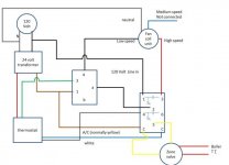
The attached picture is representative of the wires I traced. I left off a lot of the zone wires as well as the contactor wires for the A/C.

So if I understand this all, I think the relays are set up so that the middle relay will run the low speed fan circuit if the thermostat energizes the green wire. I couldn't see the relay terminal layouts and I'm not sure what terminals a and b are (assume 2 and 5) but I believe 4 and "a" are connected as N/O and that when the coil gets energized that would cause the fan to run at low speed.

Next I look at the DPDT and I see that the 2 terminal is the normally closed circuit and that the 3 terminal is the normally open. So I assume this relay is supposed to energize when A/C is on and cause the high speed fan to run while removing power from the middle relay so that the low speed fan is not energized.

OK, this sounds good but wait... look at how the DPDT relay's coil is energized???? The cool (blue, should be yellow) and heat (white) are on opposite sides of the coil (WTF??). I see the transformer is also energizing one side of the coil but white is on the other side of that (WTF!!!!) From my little bit of understanding shouldn't the transformer be on one side of the coil and the cool (blue, normally yellow) be on the other side of the coil to energize this relay for A/C????

Hmm... so not shown is the outside contactor. It is connected to the red transformer wire and the other side of the coil in the relay. I think it is the outside contactor and the blue that are energizing the coil but I haven't measured that yet.

I haven't confirmed but it looks to me like the white being connected to the DPDT relay coil is likely energizing the coil and causing my fan to run at high speed for heat and cool but again, I haven't verified this just yet.

Finally, the zone valve is getting energized whenever there is 24v going through the coil. Since it appears to me that the coil gets energized by the white wire as well as the outside contactor that whenever the thermostat calls for either heat or cool that the zone valve will get energized, and of course, that will close the contacts for the TT connections to the boiler and my boiler runs. Is this what is happening?????

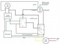
It really seems to me that the pro messed up and should have connected the brown from the transformer to one end of the DPDT relay coil and the blue (should have been yellow) cool circuit from the thermostat to the other end of the coil. Then to turn on the boiler for HEATING ONLY he should have connected one of the yellow wires to the brown at the coil as it is in the picture, white to terminal 4, and the other yellow to terminal 5. In this way the zone valve would be energized whenever the heat circuit (white) is energized and the cool circuit (coil not energized) isn't. See the proposed wiring picture.


Let me know if I'm on track here. Next up is a discussion of how I plan to clean up the rats next with a zone valve controller that I can then also use to create a priority zone for a new indirect water heater. I'd also like to run the fan coil unit off the zone valve controller but I need to work out transformer issues. I'll leave that discussion to another thread.
 

Attachments

  • existing_wiring2 (Small).jpg
    existing_wiring2 (Small).jpg
    27.4 KB · Views: 57
  • proposed (Small).jpg
    proposed (Small).jpg
    28.6 KB · Views: 53
To avoid these ads, REGISTER NOW!

fitter30

Well-known member
Joined
Jun 23, 2019
Messages
2,997
Location
Peace Valley,mo
Right diagram looks almost correct left diagram when stat call for cooling would be a direct short to common of the trans Stats w looks correct powers boiler and zone valve. But the green wire from the stat is the blower hi speed. Need relay on call for heat to power low speed blower and can't have blower power low & hi speed at the same time or it will let the smoke out. The center relay terminals 1&3 the coil? What are the contacts n.o. & n.c. and amperage of both relay contact rated for. Does that zone valve control a zone or opens and fires the boiler when theres a call for heat?
 
OP
J

jmiller_2308

Well-known member
Joined
Nov 16, 2013
Messages
566
Location
Shakopee, MN
Right diagram looks almost correct left diagram when stat call for cooling would be a direct short to common of the trans

Good catch on the direct short. I hadn't noticed that earlier. I wonder what it is doing to my transformer. Luckily cooling won't be on for a few months so that will give me a chance to sort this out before it operates that way again.

Stats w looks correct powers boiler and zone valve. But the green wire from the stat is the blower hi speed. Need relay on call for heat to power low speed blower and can't have blower power low & hi speed at the same time or it will let the smoke out.

I believe the circuit is designed such that the DPDT relay on the right is what controls whether the fan is high or low speed. When the DPDT coil is energized the fan gets high speed but the power going back to the middle relay gets de-energized (2 on DPDT to a on middle) so the low speed circuit to the fan is no longer energized even if the fan circuit (green) is energized.

When the DPDT coil is not energized no power goes to the high speed fan but power going back to the middle relay is energized. In this configuration an energized green should only result in low speed fan.

The center relay terminals 1&3 the coil? What are the contacts n.o. & n.c. and amperage of both relay contact rated for.

I don't know the configuration of the middle relay (yet) but given the diagram on the fan coil unit I believe 1&3 are its coil and that 4 & a are a normally open connection and that a & b would be a normally closed connection. I don't know the rating of the relay but once again, given the diagram on the fan coil unit I believe it is fully capable to switch 120 volts at whatever amperage the fan calls for.

The diagram on the fan coil unit only has a heat circuit and does not include the DPDT cooling circuit but in the original diagram it had 120v going to a and 4 going to the fan; it just didn't say which fan speed.

Does that zone valve control a zone or opens and fires the boiler when theres a call for heat?

The zone valve in the picture controls water going to the fan coil unit and is in essence the "forced air" zone in my system. When the zone valve opens because it gets 24v it closes contacts that drive the boiler to run. When the boiler runs it automatically starts the system pump itself rather than being triggered via another relay.

For simplicity I left 2 additional heat only floor zones out of the diagram. How they hooked into the system confused me for awhile but I think they are designed correctly.

The additional 2 zones have another transformer for their thermostats, a zone valve for each of them, and a secondary pump. The transformer, thermostat, and zone valve for each zone follow the classic configuration of transformer wired through the thermostat to the zone valve. The contact setting of each zone valve is then connected to the contact circuit of the secondary pump. The pump has TT connections that then go off to the boiler to turn the boiler on when the pump is on.

So here is the weird thing, the TT wires from the zone valve on the fan coil unit are also wired directly to the TT connections on the secondary pump. This makes sense as it allows all zones to use the common boiler TT connections. What didn't make sense to me was that the secondary pump would turn off whenever the fan coil was on. Only after digging into the relays in the diagram did I realize that the same power that comes off terminal 2 in the DPDT of the fan coil is what powers the secondary pump. In essence, the fan coil becomes a priority zone.

I just added a picture of the diagram from the fan coil for reference.
 

Attachments

  • fancoil.jpg
    fancoil.jpg
    64 KB · Views: 31
Last edited:

fitter30

Well-known member
Joined
Jun 23, 2019
Messages
2,997
Location
Peace Valley,mo
Your fan coil diagram isn't right. Y on the stat is going to common wire another short should be C on stat if it was a electronic stat. Do you want a single speed or two speed fan coil?
 
To avoid these ads, REGISTER NOW!
OP
J

jmiller_2308

Well-known member
Joined
Nov 16, 2013
Messages
566
Location
Shakopee, MN
Your fan coil diagram isn't right. Y on the stat is going to common wire another short should be C on stat if it was a electronic stat. Do you want a single speed or two speed fan coil?

I'm sorry, I'm not sure which diagram you were referencing but I think it is the black and white fan coil diagram from my last post.

That diagram was drawn and put there by the fan coil manufacture. Referencing the note just below the thermostat, I think the 1 in the square between the Y and the C common wire is meant to avoid the short you are talking about.

I do know about common wires carrying an extra 24v that can be used by smart thermostats but that isn't an issue for me, nor did the house have that wire on its original thermostat wiring.

I'd love to have multi-speed fan but the primary issue I found was that my boiler was getting triggered to run when all I wanted was cooling. I believe that if I change the wiring to be like the "proposed" wiring from my original post that I will not only correct the boiler issue but also get low speed for fan only and heating, and high speed for cooling.
 

Aileron

Well-known member
Joined
Apr 15, 2019
Messages
472
Location
outside
Just my 02. On oem diagram Y is not going directly to common, its is showing going to "note 1"by field supplied wiring which would be your cooling contractor. Y is going to wherever it is located and the other common side of its coil is going back to common. The oem diagram is only showing a single speed motor. Looks like your right diagram energizes low speed on a call for fan 'Green"and will de energize low speed for high in heat mode. May need to swap high and low speed motor leads in the right side diagram.
 

75gmck25

Well-known member
Joined
Jul 21, 2014
Messages
1,328
Location
Alexandria, VA
My thermostat controls both A/C and my boiler, so it switches between units. I noticed that the boiler was still running when in A/C position, and the boiler tech had a simple fix.

My boiler controls had a factory default minimum temp set point of 100 degrees, so it tried to keep the water at 100 degrees even if A/C was running. During the summer I have to change the minimum to 0 degrees, or just turn off the power switch for the boiler.

Bruce
 
OP
J

jmiller_2308

Well-known member
Joined
Nov 16, 2013
Messages
566
Location
Shakopee, MN
Just my 02. On oem diagram Y is not going directly to common, its is showing going to "note 1"by field supplied wiring which would be your cooling contractor. Y is going to wherever it is located and the other common side of its coil is going back to common. The oem diagram is only showing a single speed motor. Looks like your right diagram energizes low speed on a call for fan 'Green"and will de energize low speed for high in heat mode. May need to swap high and low speed motor leads in the right side diagram.

Yes, I had the same interpretation of the OEM diagram. After looking at lots of OEM suggested wiring for thermostats, valve zones, valve controllers, switching relays, etc., it appears there are several ways to connect this stuff and that the OEM diagram is just one example that the mfg supplies as guidance.

With regard to my "right" or "proposed" diagram, yes, the green energizes the low speed when the DPDT relay is in the normally closed position (1 contacts to 2).

In my "left" or "existing" diagram I agree the white (heat) circuit does energize the coil and cause the high speed fan to run.

In my "right" or "proposed" diagram I moved the white off the coil to terminal 4 as well as moving the blue (normally thermostat yellow) to the opposite side of the coil from the transformer connection to the coil. Doing this means that only the cooling circuit should energize the DPDT coil and so I believe the high speed fan should only run when cooling is called for.

If cooling is not called for than the N/C 1->2 connection on the DPDT would be engaged to supply power for the low speed fan. The low speed fan is still enabled based on the green fan wire energizing the coil in the middle relay but even if the green energizes the coil, the low speed fan will only get power when "a" is getting power from the DPDT. That is, even if green is energized, the low speed fan circuit will only get power if the thermostat is not calling for cool.

If I'm correct, then the "right" diagram should give me low speed fan for only fan on, low speed fan for heat, and high speed fan for cool. Did I miss something?

As a note, I still need to send 24v to the zone valve to open when heat is called for. I do this using the second N/C circuit in the DPDT by moving the white to 4 and the other control wire from the zone valve to 5. In this configuration when the coil is not energized (no cooling is called for) the thermostat provides 24v control signal to the zone to turn on when heat is called for and the zone valve in turn tells the boiler to turn on. When heat is not called for there is no 24v at the zone control so it closes; this is good. Finally, when cooling is called for the second circuit switches from 4->5 to 4->6 so the zone valve no longer has any chance to see 24v so my zone valve does not activate and my boiler does not fire; yay, no boiler when running A/C.

Again, I think this is correct but please let me know if I missed something.

My thermostat controls both A/C and my boiler, so it switches between units. I noticed that the boiler was still running when in A/C position, and the boiler tech had a simple fix.

My boiler controls had a factory default minimum temp set point of 100 degrees, so it tried to keep the water at 100 degrees even if A/C was running. During the summer I have to change the minimum to 0 degrees, or just turn off the power switch for the boiler.

Bruce

Interesting; this might be a backup plan for me but since I ultimately want to get to adding an indirect water heater run off the boiler I hope to resolve the issue through wiring changes if possible.
 
To avoid these ads, REGISTER NOW!
Top Bottom