

ADKAmateur
Active member
- Joined
- Feb 9, 2026
- Messages
- 40
So I built a digital readout for my Rockwell Delta 17-600 variable speed drill press that shows the spindle RPMs and thought I would share it with the Forum.
The idea for this came from when I was investigating converting a wood bandsaw to metal use (abandoned in favor of searching for a real variable speed metal bandsaw). That investigation led me to a project where the creator made an Arduino-based digital FPM gauge for their bandsaw.
After getting the 17-600 and getting it back up running (it needed a serious cleaning and new front spindle, chuck and bearings), I put a digital tach on it and saw that the actual speed was nowhere near the indicated speed on the variable speed dial (more on that later). That led me to think about using the bandsaw FPM gauge as a basis for a digital RPM gauge.
To give full credit to the original project's creator, here is a link to their work: https://www.instructables.com/Arduino-B ... eedometer/
The project consists of:
-3D printed case for the display and electronics
-3D printed holder for the Hall effect sensor
-3D printed disc to attach to the spindle shaft (holds the magnet that triggers the hall effect sensor)
-Arduino Nano
-LCD display
-On/off switch
-Potentiometer to control LCD display brightness
-Hall Effect sensor
-Wires
-Magnets
-Small perf board PCB to make up the connections
These are the 3D printed parts. Too many iterations to count! This actually took me a long time to do. I probably printed four iterations of the disc alone.

Next up was connecting everything. Here is a shot of it all wired up and installed in the case.
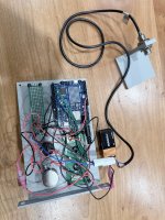
Programming the Arduino was easy - the bandsaw FPM gauge creator had posted their code and I only had to change a couple of lines to adapt it.
Here is the completed assembly prior to mounting it.

I designed the system to be non-invasive so it wouldn't alter the machine or require the drilling of any holes. I figured the two screws on the right side of the head that hold the sheet metal housing to the inside of the head would be useful for mounting the display. The Hall Effect sensor holder has magnets on the back to it attaches to the inside of the sheet metal housing. The disc with the magnet for the Hall Effect sensor sits on top of the front spindle and is held down with a nut. The nut is an old bicycle headset locknut from a friend that owns a bike shop. I couldn't find a nut with the same fine threads and Google revealed to me that old bicycle forks had the same thread pitch. Problem solved!

The machine didn't come with a cover for the top so I need to fabricate that. It will need a notch to accommodate the Hall Effect sensor, or I may replace the sensor with a lower profile version.
And it works!!! The speed on the display matches the digital tach.

Unfortunately, it confirms what my digital tach originally said - the drill is running at 2x the indicated speed that the variable speed adjustment says it should be so now I need to figure that out.
My first guess was maybe the PO had installed a motor with the wrong RPMs but that isn't the case. This leads me to believe I need to adjust/calibrate the Reeves drive assembly so that is the next project.
The idea for this came from when I was investigating converting a wood bandsaw to metal use (abandoned in favor of searching for a real variable speed metal bandsaw). That investigation led me to a project where the creator made an Arduino-based digital FPM gauge for their bandsaw.
After getting the 17-600 and getting it back up running (it needed a serious cleaning and new front spindle, chuck and bearings), I put a digital tach on it and saw that the actual speed was nowhere near the indicated speed on the variable speed dial (more on that later). That led me to think about using the bandsaw FPM gauge as a basis for a digital RPM gauge.
To give full credit to the original project's creator, here is a link to their work: https://www.instructables.com/Arduino-B ... eedometer/
The project consists of:
-3D printed case for the display and electronics
-3D printed holder for the Hall effect sensor
-3D printed disc to attach to the spindle shaft (holds the magnet that triggers the hall effect sensor)
-Arduino Nano
-LCD display
-On/off switch
-Potentiometer to control LCD display brightness
-Hall Effect sensor
-Wires
-Magnets
-Small perf board PCB to make up the connections
These are the 3D printed parts. Too many iterations to count! This actually took me a long time to do. I probably printed four iterations of the disc alone.
Next up was connecting everything. Here is a shot of it all wired up and installed in the case.
Programming the Arduino was easy - the bandsaw FPM gauge creator had posted their code and I only had to change a couple of lines to adapt it.
Here is the completed assembly prior to mounting it.
I designed the system to be non-invasive so it wouldn't alter the machine or require the drilling of any holes. I figured the two screws on the right side of the head that hold the sheet metal housing to the inside of the head would be useful for mounting the display. The Hall Effect sensor holder has magnets on the back to it attaches to the inside of the sheet metal housing. The disc with the magnet for the Hall Effect sensor sits on top of the front spindle and is held down with a nut. The nut is an old bicycle headset locknut from a friend that owns a bike shop. I couldn't find a nut with the same fine threads and Google revealed to me that old bicycle forks had the same thread pitch. Problem solved!
The machine didn't come with a cover for the top so I need to fabricate that. It will need a notch to accommodate the Hall Effect sensor, or I may replace the sensor with a lower profile version.
And it works!!! The speed on the display matches the digital tach.
Unfortunately, it confirms what my digital tach originally said - the drill is running at 2x the indicated speed that the variable speed adjustment says it should be so now I need to figure that out.
My first guess was maybe the PO had installed a motor with the wrong RPMs but that isn't the case. This leads me to believe I need to adjust/calibrate the Reeves drive assembly so that is the next project.