To avoid these ads, REGISTER NOW!

DIY install of a used Mitsubishi mini-split

Framton Nuttel

Well-known member
Joined
Jun 1, 2021
Messages
82
Location
Montreal
A couple of summers ago, I built a small backyard shed and my wife ended up using it as her home office. It is insulated and has always had heating, from a wall heater as well as heated floor. It is very cozy in the winter, but has been unbearably hot during recent summer months. There is very little shade and the shed is painted dark blue, so it can get really hot.

We looked at AC options including window-mounted units, as well as floor-standing portable units with window ducts, but the floor and window space is so limited that a small mini-split seemed to be the most attractive option.

The floor space of the shed is only around 150 square feet, but the roof and three of the walls get nearly constant sun exposure. A 9k mini split would probably be ideal, but we were able to get a used 12k Mitsubishi unit that someone local was getting rid of.

The lineset on the used unit had been cut a couple of feet from the indoor unit, but the refrigerant had been recovered into the outdoor unit. It came with around 20 feet of 1/4" and 3/8" copper lines, which was far longer than we needed.

I found a guy online who rents the gauges and vacuum pump for $20/day, and bought an eccentric flaring tube on Amazon.

There were a few downsides to getting a used mini split like this. Some cosmetic cover panels were missing, and in general we didn't get any of the stuff like wall sleeves that would be included in the "kit" if purchased new. I will try to order the cosmetic parts from Mitsubishi.

Because the copper lines had been cut near the indoor unit, I had to fashion two flare connection unions. I was able to cut the lines down to a vertical run of around ten feet, and kept the original flares and nuts at the outdoor unit end. The installation manual for this unit does not specify a minimum lineset length, and we were told that the outdoor unit should hold the nominal factory charge (no refrigerant was added to account for a longer lineset in the past).

The biggest annoyance was that the high-pressure line coming out of the indoor unit had an OD that exceeded 1/4" by around 1/32". The 1/4" flare nuts I had would not fit over this tube, and it also didn't fit correctly in the 1/4" swage block opening in the eccentric flaring tool I had purchased. It was necessary to carefully drill out the centre hole of the flare nut so that it would slip over the tubing, making sure there were no burrs or defects on the flare surface.

I made the flare on the oversized 1/4" line last, as I also had to drill out the hole in the swage block of the flaring tool so that it would grip the tubing without mangling it (the flaring tool gripped the longer section of 1/4" line no problem, so I did that before drilling). To be safe, I applied some Nylog Blue to all of the flare surfaces.

I purged and pressure tested using MIG welder gas (25%CO2/balance Argon, ∼zero moisture/hydrocarbons). The best regulator I could find for this tank only went up to 150psi, but it's better than nothing and I didn't get any bubbles or pressure drop in around four hours.

I then pumped down to 30 inHg vacuum, closed the valve, and left it for a couple more hours. There were no apparent leaks, although my testing is evidently not perfect.

I released the refrigerant into the lines, powered everything on, and it seems to be working ok. I had some frost on the high pressure line before wrapping everything with insulation, but the outdoor humidity here is like 90% and apparently this can be normal in high ambient humidity.

It's been around a week and the unit is still cooling nicely - it is extremely quiet. I'm curious as to why the high-pressure line on the Mitsubishi is larger than 1/4" - perhaps it's some metric standard or a larger wall thickness?

Time will tell if this budget installation will hold up, but overall the financial risk was pretty low. Most of the work went into removing wall panelling so I could run wiring and the lineset, while maintaining integrity of the insulation, weather sealing, and vapour barrier. Overall budget was a couple hundred dollars for stuff like wiring and the flaring tool.

If our "recycled" mini split system doesn't work out, another unit could be dropped in with minimal additional work since the wiring and wall penetrations are already there.

I will try to post a few photos of the project below.
 
Last edited:
To avoid these ads, REGISTER NOW!
OP
F

Framton Nuttel

Well-known member
Joined
Jun 1, 2021
Messages
82
Location
Montreal
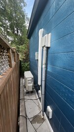
Outdoor unit installed. I still need to secure the drain pipe and anchor the outdoor unit better, although it is almost completely silent and does not vibrate at all.

7C3A6063-9223-434F-9A95-8A809B78D86E_1_105_c.jpeg
 
OP
F

Framton Nuttel

Well-known member
Joined
Jun 1, 2021
Messages
82
Location
Montreal
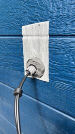
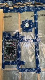
Wiring from sub panel to outdoor disconnect box.

37145496-953B-424D-BEB5-6C90D384601B_1_105_c.jpeg 00282D8C-70BE-46A8-AC71-9FB707054EEE_1_105_c.jpeg

I used NMWU 14/2 cable between the panel and the outdoor disconnect. The breaker is a 2-pole 15A breaker as indicated on the name plate of the outdoor unit. Minimum circuit ampacity is specified at 12A.

Between the disconnect and the outdoor unit, I used the same NMWU 14/2 cable inside a 1/2" water tight whip.

I could not find NMWU 14/2 with black & red insulated conductors in my area, so I wrapped the white wire in red tape at both ends.

I ran 14/3 stranded SJOOW wire between the indoor and outdoor units, as this wiring run is relatively easy to inspect and access.

After wiring everything up I applied a good bead of silicon sealant along the sides and top of the disconnect box, leaving the bottom open.
 
Last edited:
OP
F

Framton Nuttel

Well-known member
Joined
Jun 1, 2021
Messages
82
Location
Montreal
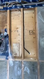
This used unit did not come with a "wall sleeve" so I improvised using some 3" ABS pipe and a closet flange.

I used a pair of concentric hole saws to remove the lip inside the flange, so that the 3" pipe could pass fully through the flange. This allowed it to be securely mounted against the exterior wall, from the inside. I cut a couple of 5 degree shims to give it a downward angle.

tempImageQyIAxZ.png tempImaget4Wrpz.png tempImagedgoDHx.png tempImageNXbykB.png

After the photos were taken I applied silicone sealant around the outside lip of the sleeve on the exterior wall. The final installation also included a duct hood with additional silicone sealant around the top and sides.

Once everything was in place, I put back the insulation and vapour barrier.

We had some record-breaking rainfalls in the last week and happily there has been zero water ingress.
 
OP
F

Framton Nuttel

Well-known member
Joined
Jun 1, 2021
Messages
82
Location
Montreal
A few more photos of the installation:

tempImageQhP7za.png A6370F1D-B08A-444F-B8C0-61A38FF93CEB_1_105_c.jpeg 8C31CBD6-1298-4400-A1D7-23E245D4563A_1_105_c.jpeg 0CBC5E46-ED32-4686-A99D-E3A152637BAC_1_105_c.jpeg

The cover panel for the lower right corner of the indoor unit was missing and I'll have to see if I can order it or maybe 3D print something.

The sheet metal lip visible along the lower edge of the unit, in the centre photo, should go inside the plastic casing.

After everything else was installed, I stuffed a plug of mineral wool insulation into the sleeve and plugged both ends with electrician's putty.
 
Last edited:
OP
F

Framton Nuttel

Well-known member
Joined
Jun 1, 2021
Messages
82
Location
Montreal
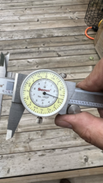
As I mentioned in the original post, the OD of the high-pressure line from the indoor unit was slightly larger than 1/4" (calliper shows OD).

tempImage3zB338.png tempImagemGewX4.png

Attempting to use my (imperial units) flare tool resulted in a nasty flare that had to be cut off and had to be redone after some modifications to the flare nut and flare tool.
 
OP
F

Framton Nuttel

Well-known member
Joined
Jun 1, 2021
Messages
82
Location
Montreal
To adapt for the oversized high-pressure line, I drilled out the centre hole on the flare nut on that side. The tube diameter was 9/32" so I made the new hole oversized by 1/64" (19/64" diameter bit).

After doing the flare on the nominal 1/4" line to the outdoor unit, I drilled out the swage block of the flaring tool set. I made it 1/64" under the measured tube diameter (17/64") so it would grip the tube without excessive deformation (this is the same size offset as used in the unmodified tool - swage block is smaller than the actual 1/4" tubing by around 1/64").

tempImage7uXY5m.png 69992C2F-4D09-48B7-883C-37CDE5285431_1_102_a.jpeg

After drilling out the flare nut, I inspected under high magnification to make sure there were no burrs or other defects.

The modified flaring tool worked fine for the oversized tubing and the flare looked good.
 
Last edited:
OP
F

Framton Nuttel

Well-known member
Joined
Jun 1, 2021
Messages
82
Location
Montreal
After hooking everything up, I did some crude pressure tests using the MIG welder gas and then evacuated the lines.

I closed the valve to the pump, and left the vacuum gauge on for a couple of hours (although admittedly this is a pretty mild test given the 600psi design pressure of the system).

tempImagefT6N4d.png
 
OP
F

Framton Nuttel

Well-known member
Joined
Jun 1, 2021
Messages
82
Location
Montreal
After releasing the refrigerant I did some additional bubble tests but did not see any evidence of leaking.

When I turned the unit on, I noticed frost on the high-pressure line where I had not yet replaced the insulation. This can be a sign of a refrigerant leak, or low charge, but it may also be normal given that the relative outdoor humidity was around 90%. I will keep an eye on things.

1FE0F14F-0777-4FC8-B420-8DA8594A9BF7_1_105_c.jpeg
 

pcmeiners

Well-known member
Joined
Aug 13, 2009
Messages
7,964
Location
In the only town in Pennsylvania, Bloomsburg.
"Attempting to use my (imperial units) flare tool resulted in a nasty flare that had to be cut off and had to be redone after some modifications to the flare nut and flare tool."

Ran into the same issue with my Husky flare tool , not as bad, used my Foredom flex tool and a grinding stone to remove some metal from the swage block, came out well.
 
To avoid these ads, REGISTER NOW!
OP
F

Framton Nuttel

Well-known member
Joined
Jun 1, 2021
Messages
82
Location
Montreal
Ran into the same issue with my Husky flare tool , not as bad, used my Foredom flex tool and a grinding stone to remove some metal from the swage block, came out well.

Thanks - was your mini split also a Mitsubishi? The weird thing is that my tool worked perfectly on the longer portion of the 1/4" line. I have no idea how these were joined when the unit was last in use, or even if this is the same lineset.

I wonder if the 1/4" lines used by Mitsubishi have a thicker wall than the "utility grade" copper pipes you might buy at a big box store. There was no problem at all on the 3/8" side though.
 
OP
F

Framton Nuttel

Well-known member
Joined
Jun 1, 2021
Messages
82
Location
Montreal
Overall the unit is cooling and dehumidifying nicely and (most important) my wife is happy ;).

BF607222-DA2C-48D5-B3CE-A74889955D20_1_201_a.jpeg

I am hoping that the "oversizing" of the unit, in terms of square footage, may be offset somewhat by the fact that the shed is basically a dark coloured box sitting in direct sun all day.

The floor is also around an inch of self-levelling compound for the heating system, and has a pretty high thermal mass.
 

American Locomotive

Well-known member
Joined
Jan 8, 2017
Messages
11,016
Location
Rhode Island
I would say frost is probably not normal on that line, and is suggestive of a low charge. I don't recall seeing frost on that line on any of the minisplits I've installed. The unit is oversized for that space, but it won't be too big of a deal because it is (hopefully) an inverter unit. A 6,000 BTU unit would easily cool 150 sq ft.
 
OP
F

Framton Nuttel

Well-known member
Joined
Jun 1, 2021
Messages
82
Location
Montreal
I would say frost is probably not normal on that line, and is suggestive of a low charge.

Agreed - I'm going to keep an eye on it. The gauge set I borrowed to vacuum the lines did not have the right pressure range for checking charge on R410A, but now that we have the basic installation going I might spring for one or just hire a pro to check it.

There are other basic things as well, like checking if any of the coils or vanes are dirty. Given that this was basically a discarded unit, it's possible that either the charge was already low or that some of the coils need a good cleaning.
 
OP
F

Framton Nuttel

Well-known member
Joined
Jun 1, 2021
Messages
82
Location
Montreal
The unit is oversized for that space, but it won't be too big of a deal because it is (hopefully) an inverter unit. A 6,000 BTU unit would easily cool 150 sq ft.

Yes it's an inverter unit - the compressor speed is continuously variable so that was our thinking, that it would not be a huge issue for the small space. In operation, you can see this in effect as the outdoor unit appears to be barely working even though it is cooling quite effectively inside.

The submittal sheet for this model gives a cooling range of 2,800 to 12,000 Btu/h. For heating its 3,000 to 21,000 Btu/h. The beauty of an inverter-based system is that it's not going crazy cycling on and off, but can throttle down to whatever speed is appropriate.

We wanted to find something used and smaller units are extremely rare. If I ever do find a smaller one, I might use it for the shed as I have other places where the 12k might be good.
 
Last edited:

mobiledynamics

Well-known member
Joined
Mar 14, 2010
Messages
5,052
Location
Gotham City
Frantom -

Just a tidbit if you haven't shone a light inside the blower housing. It's not a bad idea to remove cover, Remove blower wheel . Blower wheel might be dusty but the back housing does get icky with small black mold if it doesn't dry out during operation IME. These days do need cleaning ......to the blind eye that may not see the ickiness of build up
 
OP
F

Framton Nuttel

Well-known member
Joined
Jun 1, 2021
Messages
82
Location
Montreal
Frantom -

Just a tidbit if you haven't shone a light inside the blower housing. It's not a bad idea to remove cover, Remove blower wheel . Blower wheel might be dusty but the back housing does get icky with small black mold if it doesn't dry out during operation IME. These days do need cleaning ......to the blind eye that may not see the ickiness of build up

Thanks! If I was smart, I would have done a cleaning before installing the system. Unfortunately there was a narrow window to do the installation without disrupting use of the shed as an office...
 

mobiledynamics

Well-known member
Joined
Mar 14, 2010
Messages
5,052
Location
Gotham City
Thanks! If I was smart, I would have done a cleaning before installing the system. Unfortunately there was a narrow window to do the installation without disrupting use of the shed as an office...

I see. Well, with the unit one - vanes open....shine a light up in area. It should give you a glimpse of both the back of the housing and the blower.....blowing black mould ain't exactly healthy...
 

American Locomotive

Well-known member
Joined
Jan 8, 2017
Messages
11,016
Location
Rhode Island
Agreed - I'm going to keep an eye on it. The gauge set I borrowed to vacuum the lines did not have the right pressure range for checking charge on R410A, but now that we have the basic installation going I might spring for one or just hire a pro to check it.

There are other basic things as well, like checking if any of the coils or vanes are dirty. Given that this was basically a discarded unit, it's possible that either the charge was already low or that some of the coils need a good cleaning.
You cannot check charge pressures on a minisplit (at least easily). The small "high pressure" line coming out of a minisplit isn't actually the high side. It's after the expansion valve, so it is also low pressure, just like the large line.

The only way to verify charge in a minisplit is to **** all of the charge out, and weigh in a fresh charge based on the data plate.
 
OP
F

Framton Nuttel

Well-known member
Joined
Jun 1, 2021
Messages
82
Location
Montreal
You cannot check charge pressures on a minisplit (at least easily). The small "high pressure" line coming out of a minisplit isn't actually the high side. It's after the expansion valve, so it is also low pressure, just like the large line.

The only way to verify charge in a minisplit is to **** all of the charge out, and weigh in a fresh charge based on the data plate.

Yeah I'd heard something to that effect, although some people seem to attempt it anyway based on pressure (maybe it can show gross issues even if it's not completely quantitative). Since I don't have the gauge, and it may not be useful anyway, I will just see how it runs in the coming weeks. We've had very hot weather recently and it seems to be cooling fine. There is also no more frost evident - it was just doing that the day I first ran it when the lines were not fully insulated yet.

Is there a "correct" surface temperature for the two lines? This could be measured with a thermal camera, I suppose.
 
To avoid these ads, REGISTER NOW!
Top Bottom