
franksinatra
Well-known member
I ran a 100amp subpanel to my garage sometime back and Im finally getting to the wiring. Heres what I have. Two breakers, each running 5 dual gang boxes (10 outlets) for each side of the garage. I have wired them with 12-2 for 20 amp circuits (correct term?) I would like to know if I can just hook up the grounds on the line in and the line out (Picture) or am I supposed to pigtail from each receptacle to line in line out, combining 4 grounds?
Second question. The homeowner before me ran 2 15 amp outlets to the outside of the house and connected the 2 garage door openers to it. These are the only things on the 15 amp breaker. Is this ok? Do I need to worry about adding a GFI?
Finally I would like to know if everything in my subpanel looks OK. I thought I remember someone saying that the grounds in a panel shouldnt be split up but my electrician said it would be OK. I want the box as clean looking as possible so If anyone has any suggestions on how it could be cleaned up, please let me know. Oh, one more thing are the plastic romex connectors what everyone is using now? I still need a metal one for my 6-3 220 line correct? Thanks, G
Second question. The homeowner before me ran 2 15 amp outlets to the outside of the house and connected the 2 garage door openers to it. These are the only things on the 15 amp breaker. Is this ok? Do I need to worry about adding a GFI?
Finally I would like to know if everything in my subpanel looks OK. I thought I remember someone saying that the grounds in a panel shouldnt be split up but my electrician said it would be OK. I want the box as clean looking as possible so If anyone has any suggestions on how it could be cleaned up, please let me know. Oh, one more thing are the plastic romex connectors what everyone is using now? I still need a metal one for my 6-3 220 line correct? Thanks, G
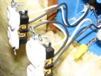

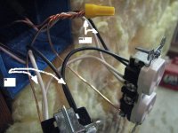

 Now I need to redoe 12 others. lol