rslaback
Well-known member
At work we have a somewhat regular task which entails installing a hydraulic pump set into a reservoir that is obstructed from the top but has a side access panel. The pump assemblies are anywhere from 60 to 120 pounds and you are trying to remove and reinstall them overtop of a pan 5 or so inches deep with hydraulic oil. An overhead crane exists that covers the entire footprint of the room. The ergonomics of this job absolutely **** and there is a fairly high mode of failure as it can be difficult to get the gaskets in place correctly when balancing and bolting it in.
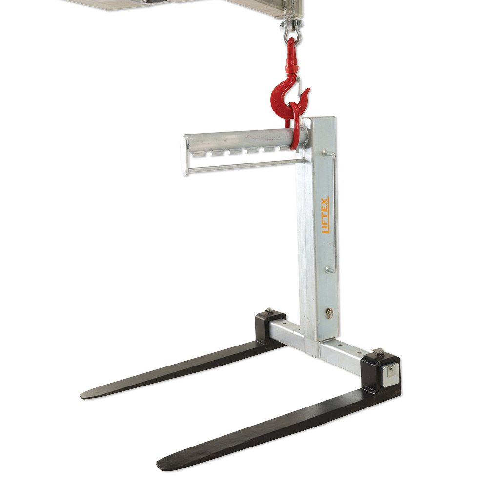
Has anyone ever seen a commercially available offset lift arm similar to an obstruction style wrench but much bigger? Something that would allow us to use the crane from above but still be able to slide the pump in through the side access and then support it?
In my kindergarten CAD below the machine would be in green. The proposed lift arm would be yellow.

Custom building this isn't out of the question but our safety group is going to be much more comfortable with a pre-built commercial solution than they are with us having the engineering math done to determine load ratings. I've never seen one but that doesn't mean it doesn't exist.
Because this is GJ and the land of the second guessers, allow me to add some more facts:
Has anyone ever seen a commercially available offset lift arm similar to an obstruction style wrench but much bigger? Something that would allow us to use the crane from above but still be able to slide the pump in through the side access and then support it?
In my kindergarten CAD below the machine would be in green. The proposed lift arm would be yellow.
Custom building this isn't out of the question but our safety group is going to be much more comfortable with a pre-built commercial solution than they are with us having the engineering math done to determine load ratings. I've never seen one but that doesn't mean it doesn't exist.
Because this is GJ and the land of the second guessers, allow me to add some more facts:
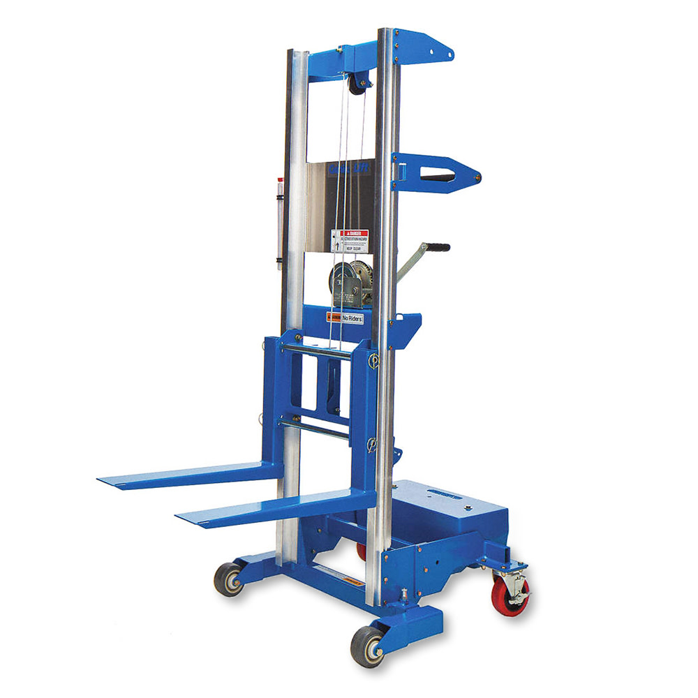
- The heights are different on each machine so a cart isn't a great solution.
- The pump assemblies do have hanging eyes on the top of them.
- There is not good access underneath the machines to make a C style cart
- It is necessary for the technicians to be able to adjust the height of the pump assemblies during the installation process.
- Draining the hydraulic tanks is not an option.
- The top of the reservoir does also open.
- Removing the items above the reservoir is not an option.