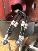
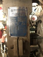
The motors spin good when I do it by hand, no roughess. I forgot to take a pic from the wiring label, but according to the label, the motor it’s wired to 110v. The tape was me to identifying the wires.
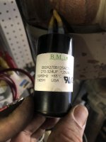
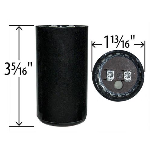
My first thought was if the capacitor have l enough uF’s to start the motor, that’s why I post the first pic at the beginning of the post. I’m working with one cap, since the drill motor came with no cap. I tested the cap with my multimeter and it’s good. According to this chart, I’m not using the right cap. What do you think??
According to what I googled, a 1hp motor it’s around .746 Kw. At 110v. So, it needs a cap with 500-580 uF’s to start properly. Is this right?
I don't know the cap size or remember it, I am suspecting you might be right, but that youtube video will work for your troubleshooting.
I would verify your winding with an ohm meter first before starting... and you might have to verify the centrifugal switch inside as well...
This is what I did when I dig my motor out to rewired it for reversible. Doesn't matter, troubleshooting is still the same for you or at least modify to fit you.
this link...have the name plate which shows it is almost the same configuration as yours for a Drill press motor.. except mine is 1/2 HP.
https://www.garagejournal.com/forum/showthread.php?t=361242&highlight=reverse
basically you wanted this it have more info.
https://www.practicalmachinist.com/...please-wiring-switch-motor-257832/index2.html
These drill press motor are usually wired for one direction only, if it is a dual voltage, it means your motor have two run coils w1 AND w2 and it is made to be run in one direction only so the start coil W3 (connections) will be permanent embedded to the run coils.
What I learned from that mod is W1 resistance = W2 +/- very small percentage.. might be due to my not so accurate meter. It shouldn't be way way off. W3 = W1+W2 again within a a reasonable range... In my case W1 = 8 ohm W2 = 8.05 ohm and W3 is 16.1 Ohm... if I remember correctly... They are independent coils...
Review the diagram on that practicalmachinist site... and what I did was
take out the capacitor leave those wire hanging... then measure the 4 wires 1&2 it should be one of the run coil, lets just say W1... and then measure 3 & 4 it should be the another run coil lets say W2...
W3 is harder to measure because the other end is embedded inside for these motors usually...but if you look at the practicalmachinist site for the drawings ... you'll see W3 is connected one end to the Plugs L1 or L2... then to the coil to a capacitor then the centrifugal switch... or maybe to a centrifugal switch then to the cap. So you should be able to make a measurement from one of the disconnected capacitor wires and to one end of the L1 or L2 connections in this case it's your 1 or 4 wires.
Once you verifying the coils and wiring, then I would try to verify the last piece the centrifugal switch, but requires opening up the motor... it's usually a mechanical switch... plenty of youtube videos on this as well...
if all else checked out, maybe decided to try a bigger cap.
When testing the motor try not to hook up the belt at first and make sure it spins and spins up to speed without hesitation.
good luck... YMMV of cause, dependents on your level of comfort digging into these things.
I might have a HF 1hP general purpose motor somewhere in the garage that I can verify the capacitance as a reference... If I get off my coach to look for it.
If I remember anything else, I'll add... but that practical machinist link is all I used.