Greetings.
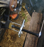
Alrighty, not looking forward to drilling and tapping this crankshaft gear to remove it, but that seems to be the preferred method (or splitting it) but if I'm gonna do it, I'd like to do it as close to right as my means will allow! What's the best way for a shadetree to make sure the holes are straight/perpendicular to the gear face? Perhaps using something like flange bushings to guide the drill bit(s)? Thanks in advance!

Alrighty, not looking forward to drilling and tapping this crankshaft gear to remove it, but that seems to be the preferred method (or splitting it) but if I'm gonna do it, I'd like to do it as close to right as my means will allow! What's the best way for a shadetree to make sure the holes are straight/perpendicular to the gear face? Perhaps using something like flange bushings to guide the drill bit(s)? Thanks in advance!


")