To avoid these ads, REGISTER NOW!

Dummy needing advise

aalleexx

Well-known member
Joined
Apr 22, 2008
Messages
136
Location
East Texas
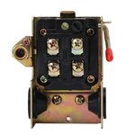
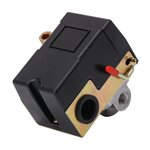
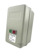
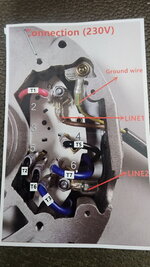
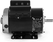
I have searched the forum until I am thoroughly confused. I am trying to piece together a compressor for a good 60gal tank I was gifted. I have a harbor freight 5hp pump and a 5hp single phase elect motor. I picked up a mag starter and pressure switch from amazon(pics below). In the process of mounting pump and motor to tank. I need advise on wiring the mag starter and pressure switch to the motor. I have a 30amp 230v receptacle box reserved for the project. Please help me understand which wires go to the different connections. I looked at so many different setups, I am thoroughly confused now! I know an electrician is my best bet and may have to go that route if unable to get it setup, but really want to try to do it to learn. Any help greatly appreciated, sorry for the long post.
 

Attachments

  • 1a.jpg
    1a.jpg
    43.7 KB · Views: 67
  • 1.jpg
    1.jpg
    103.3 KB · Views: 72
  • 22.jpg
    22.jpg
    87.5 KB · Views: 58
  • 22a.jpg
    22a.jpg
    118.8 KB · Views: 44
  • 1c.jpg
    1c.jpg
    116.2 KB · Views: 43
  • motor printed inst.jpg
    motor printed inst.jpg
    377.5 KB · Views: 15
  • motor .jpg
    motor .jpg
    687.5 KB · Views: 16
To avoid these ads, REGISTER NOW!

wyliesdiesels

Well-known member
Joined
Aug 14, 2012
Messages
19,994
Location
Modesto, CA
the 30a receptacle will not work for that. you need to hardwire it

also is that a handy box that the mag started is mounted in? box is way too small...
 

ycgoat

Well-known member
Joined
Mar 28, 2020
Messages
971
Location
S.E. Va
I would connect 240v from panel to L1 and L3 of the starter;
Then T1 and T3 of the starter to the Line side of the pressure switch.
From the Load side of the pressure switch go to the motor as shown on the diagram on the motor label where 1 wire ties to wire #1 and the other to #6.

Edit: it looks like it wants a coil voltage, so you could tap off the 240 at L1 and L2 and break that through the pressure switch instead of having it between the starter and motor.

All 3 components need to be grounded to the equipment grounding conductor coming from the panel. You could install and wire up one device at a time and test it as you go. such as put power to the starter and verify you get 240 between T1 - T3 and that the green button starts it and the red button stops it. Then hook that to the pressure switch and so on.
 
Last edited:

wyliesdiesels

Well-known member
Joined
Aug 14, 2012
Messages
19,994
Location
Modesto, CA
I would connect 240v from panel to L1 and L3 of the starter;
Then T1 and T3 of the starter to the Line side of the pressure switch.
huh? T1 and T3 are the contactor outputs to the overload relay block. you dont wire a pressure switch to those.

From the Load side of the pressure switch go to the motor as shown on the diagram on the motor label where 1 wire ties to wire #1 and the other to #6.
Huh? you dont run the motor load thru the pressure switch. thats the job of the contactor. the pressure switch only handles the coil load.

The pressure switch needs to connect to one side of the coil, the one not connected to the overload relay, and the corresponding line in.

Edit: it looks like it wants a coil voltage, so you could tap off the 240 at L1 and L2 and break that through the pressure switch instead of having it between the starter and motor.
you would never wire a pressure switch between a contactor and the motor. whats the point of that? defeats the whole purpose of the starter and is a good way to burn up your pressure switch.

have you ever worked on motor starters? doesnt sound like it
All 3 components need to be grounded to the equipment grounding conductor coming from the panel. You could install and wire up one device at a time and test it as you go. such as put power to the starter and verify you get 240 between T1 - T3 and that the green button starts it and the red button stops it. Then hook that to the pressure switch and so on.
no you should be verifying at the output of the overload relay since that is where the motor will connect.
 

ycgoat

Well-known member
Joined
Mar 28, 2020
Messages
971
Location
S.E. Va
huh? T1 and T3 are the contactor outputs to the overload relay block. you dont wire a pressure switch to those.


Huh? you dont run the motor load thru the pressure switch. thats the job of the contactor. the pressure switch only handles the coil load.

The pressure switch needs to connect to one side of the coil, the one not connected to the overload relay, and the corresponding line in.


you would never wire a pressure switch between a contactor and the motor. whats the point of that? defeats the whole purpose of the starter and is a good way to burn up your pressure switch.

have you ever worked on motor starters? doesnt sound like it

no you should be verifying at the output of the overload relay since that is where the motor will connect.
You are hard on some body; The diagram labeling is the same on both sides of the overloads 2T1, 4T2, and 6T3, so If T1 and T3 are incorrect what are they labeled as? Compressors are wired up with the pressure switch as the only control all the time, Initially I did not see the coil in the diagram and considered it just a switch, so when I noticed it I edited it to break the starter control through the pressure switch.
 

wyliesdiesels

Well-known member
Joined
Aug 14, 2012
Messages
19,994
Location
Modesto, CA
You are hard on some body; The diagram labeling is the same on both sides of the overloads 2T1, 4T2, and 6T3, so If T1 and T3 are incorrect what are they labeled as? Compressors are wired up with the pressure switch as the only control all the time, Initially I did not see the coil in the diagram and considered it just a switch, so when I noticed it I edited it to break the starter control through the pressure switch.
If you look at the OPs pics youd see the OL relay doesnt have labels. So then the op is gonna think he needs to wire the motor in before the OL relay
 

fitter30

Well-known member
Joined
Jun 23, 2019
Messages
2,966
Location
Peace Valley,mo
Need a pic of starter cardboard box tag. Did u buy motor starter overloads and coil? Your looking for a simple easy to read diagram?
 

Norcal

Well-known member
Joined
Mar 16, 2008
Messages
13,752
A starter by it's name means it has a O/L relay without one it's would only be a contactor. the OP's photo shows a O/L relay behind a funky cover control kit which is not needed nor wanted with a compressor, for the application 2-wire control is what would be used.
 

mogandave

Well-known member
Joined
Nov 4, 2021
Messages
3,052
Location
Bangkok
OP, does the tank already have a pop-off valve? If not, you will need to get one.

Were it me, I would set the compressor up using an ordinary switch to get it operational. With the switch, and a pressure gage installed. you can make sure the compressor is actually pumping, and you can test the pop-off valve is in actually popping-off.

PAY ATTENTION. Do not let it run unattended. During testing, the motor runs unprotected, so make sure it is not getting hot, stinking or smoking.

Once the compressor is functional, install and test the pressure switch to make sure it's working. The pressure switch turns the starter off and on.

The starter turns the motor off and on.

It is easier to test the components and figure out how they work individually rather than trying make them all work together. Once you figure out how the contactor turns off and on, it's just a matter of hooking them up.

I assume you have a multi-meter and know how to use it. If you do not, stop here, and get someone to help you.

I would get a switch like this and install test-leads to it that will allow you to just use wire-nuts to hook it up. You can use the same switch to test the contactor. When you're done, save it to use for your next project, assuming you don't electrocute yourself...


Switch.jpg

Pop-Off.jpg

The pop-off should be about 10-20 psi more than your operating pressure/pressure-switch, and much less than the tank rating? What is the tank rated for?
 

AntonLargiader

Well-known member
Joined
Nov 20, 2016
Messages
1,372
Location
Charlottesville, VA
Norcal has it right; you'd want to bypass that starter's typical self-latching control scheme it has and use it as a big relay (or get a different contactor assembly). It is set up for momentary contacts and you are wanting to operate it with a maintained contact in the pressure switch, so you'd want the switch to be fed by L1 and L3 and ...
The pressure switch needs to connect to one side of the coil, the one not connected to the overload relay, and the corresponding line in.
 

wyliesdiesels

Well-known member
Joined
Aug 14, 2012
Messages
19,994
Location
Modesto, CA
Norcal has it right; you'd want to bypass that starter's typical self-latching control scheme it has and use it as a big relay (or get a different contactor assembly). It is set up for momentary contacts and you are wanting to operate it with a maintained contact in the pressure switch, so you'd want the switch to be fed by L1 and L3 and ...
bingo. i totally forgot to mention the latching circuit.... dont need that on a compressor. the pressure switch takes care of that.
 

AntonLargiader

Well-known member
Joined
Nov 20, 2016
Messages
1,372
Location
Charlottesville, VA
How can he use the off-on buttons on the motor-starter to energize the pressure-switch?
You could take the yellow wires off terminals 13 and 14, and then use those wires to latch and unlatch a different relay that feeds the switch. Advantage would be that it's not going to turn itself back on if the power is cycled or something (that's the beauty of the self-latching approach). You'd basically be building a miniature version of what is already there, though, and you can just buy that already packaged.

As it is now, not possible. The latching function works through contacts that move with the main pole of the starter. That moves to turn the motor on and off, which is different than what you would want for energizing the pressure switch.

Those extra contacts that you see in there can be used for indicator lights to show if it's running or has overloaded. Not needed for this as it's pretty obvious when the compressor is running, but if you repurposed 13 and 14 for an addition relay to latch the switch power, you'd want to configure a light so you knew when there was power to the switch, as it wouldn't be otherwise obvious.
 

mogandave

Well-known member
Joined
Nov 4, 2021
Messages
3,052
Location
Bangkok
You could take the yellow wires off terminals 13 and 14, and then use those wires to latch and unlatch a different relay that feeds the switch. Advantage would be that it's not going to turn itself back on if the power is cycled or something (that's the beauty of the self-latching approach). You'd basically be building a miniature version of what is already there, though, and you can just buy that already packaged.

As it is now, not possible. The latching function works through contacts that move with the main pole of the starter. That moves to turn the motor on and off, which is different than what you would want for energizing the pressure switch.

Those extra contacts that you see in there can be used for indicator lights to show if it's running or has overloaded. Not needed for this as it's pretty obvious when the compressor is running, but if you repurposed 13 and 14 for an addition relay to latch the switch power, you'd want to configure a light so you knew when there was power to the switch, as it wouldn't be otherwise obvious.

Thanks!
 
To avoid these ads, REGISTER NOW!
OP
A

aalleexx

Well-known member
Joined
Apr 22, 2008
Messages
136
Location
East Texas
Sorry to kick a dead horse, but, I am back to try and hook up my Frankenstein compressor. 60 gal tank, Ebay 5hp motor, HF 5 HP, 145 PSI V-Style Single Stage Cast Iron Air Compressor Pump, Mag starter with run, stop buttons on front of case and I need advice on wiring the mag starter and pressure switch to the motor. I have a 30amp 230v junction box reserved for the project. I would like to use the buttons on the mag starter to start and stop the compressor, if possible. Please help me understand which wires go to the different connections. I looked at so many different setups, I am thoroughly confused now! I know an electrician is my best bet and may have to go that route if unable to get it setup, but really want to try to do it to learn. Any help greatly appreciated, sorry for the long post. Re-posting pics below. P.S. any drawings or sketches would help someone like me.
 

Attachments

  • 1c.jpg
    1c.jpg
    116.2 KB · Views: 15
  • 1b.jpg
    1b.jpg
    61.7 KB · Views: 14
  • 1a.jpg
    1a.jpg
    43.7 KB · Views: 13
  • 20230530_131158.jpg
    20230530_131158.jpg
    488.2 KB · Views: 14
  • motor printed instructions.jpg
    motor printed instructions.jpg
    377.5 KB · Views: 13
  • 60754_W3.jpg
    60754_W3.jpg
    125.7 KB · Views: 13
  • 1.jpg
    1.jpg
    103.3 KB · Views: 12
  • motor .jpg
    motor .jpg
    687.5 KB · Views: 16
  • 22.jpg
    22.jpg
    87.5 KB · Views: 16
  • 22a.jpg
    22a.jpg
    118.8 KB · Views: 19

AntonLargiader

Well-known member
Joined
Nov 20, 2016
Messages
1,372
Location
Charlottesville, VA
You want to use those buttons each and every time the compressor has to run to rebuild pressure? Or you are hoping to use them as master on/off and let the pressure switch turn it on and off as needed?
 

Norcal

Well-known member
Joined
Mar 16, 2008
Messages
13,752
That "SPL" motor is not a 5 HP motor if it was it would say so.
 

AntonLargiader

Well-known member
Joined
Nov 20, 2016
Messages
1,372
Location
Charlottesville, VA
I addressed that option previously. Those are momentary pushbuttons that are not really suitable for this use unless you have them acting on a master control relay (that you would need to add) that energizes the pressure switch. If you were comfortable with doing that you probably wouldn't be here asking, though.

Simple version: you are looking for a master on/off switch. Those pushbuttons do that by latching the mag starter directly. However, you need the pressure switch to control the mag starter directly, which means you need something that interrupts power to (or from) the pressure switch. Therefore those momentary buttons don't have anything to independently act on. You would have to have them act on something else, as they are by design for latching a circuit rather than switching a circuit. They would have to latch something else other than the mag starter.

Unless there is a clever way to integrate them that doesn't occur to me right now. But we gave you all of this info before... did you process it?

EDIT: to clarify what latching is... momentary pushbuttons like that don't save any kind of positions the way a light switch does. The start button pulls in the mag starter, and the mag starter holds itself closed until something else makes it release. That something else is an interruption of current through the stop button when you push it. When you let go of the stop button it closes again but since the starter has opened up again by then it doesn't stay pulled in until you press start again.

Switches like the pressure switch or a light switch are considered persistent or maintained contacts. The pressure switch would do the job by applying power to the starter coil, and when that power goes away it opens up again. The switch would be wired differently to the starter so that it does NOT latch. It's this mixture of latching and maintained that is complicating the idea of using those buttons for master control. Because the pressure switch is constantly cutting in and out, and pulling and releasing the starter, you need something persistent to say RUN or DON'T RUN. Not something momentary.
 
Last edited:

WFWilson

Member
Joined
May 30, 2023
Messages
5
Location
West Virgina
Hi, Retired electrician here. You do not need a starter. The motor you have has built in overload protection. Motor leads to the pressure switch power to the switch, you can add a 2 pole switch if you want.

30 amp circuit. 10 wag wire

Make sure you have a check valve between the compressor and tank. This keeps your pump alive by not have constant pressure on the head.
 
OP
A

aalleexx

Well-known member
Joined
Apr 22, 2008
Messages
136
Location
East Texas
Hi, Retired electrician here. You do not need a starter. The motor you have has built in overload protection. Motor leads to the pressure switch power to the switch, you can add a 2 pole switch if you want.

30 amp circuit. 10 wag wire

Make sure you have a check valve between the compressor and tank. This keeps your pump alive by not have constant pressure on the head.
Thank you, it's starting to make more sense to me now. Where would the 2 pole switch go?[wiring wise| in the setup?
 

WFWilson

Member
Joined
May 30, 2023
Messages
5
Location
West Virgina
Thank you, it's starting to make more sense to me now. Where would the 2 pole switch go?[wiring wise| in the setup?
You can add the two pole switch in a place that is easy to get to if you cannot get to the compressor readily. The purpose of the switch is simply a more convenient place to turn the compressor on and off. For example I have an 80 gallon Ingersol Rand 2 stage, it’s a monster and lives in it own area that is separate from my main garage.

I have mine hard wired but because there is not a disconnect means within sight of the compressor I have a 30 non fusable disconnect right next to the compressor so when I need service it I can be sure the power is off. But I also have a 2 pole switch next to the man door going into the garage so I can turn the compressor on and off when I enter or leave. I also have an automatic purge valve to drain the tank for a second or so every time it cycles.

Dry shop air is a must have. Water is the number one compressor tank killer and it does not take long to build up. I also have a main desicate dryer as well as oil / water separators. On a hot humid day when I am working in the shop a lot it is not uncommon to drain half a gallon of water.

Water will also ruin a paint job and destroy air tools.

Make sure you check your pump rotation and make sure the motor is turning it correctly. Your default on your motor is ccw. Most pumps are ccw as well but double check. You can change the rotation direction of your motor by swapping two leads. Hit me up if you have any other questions. Most of all be safe. It’s tempting to cobble something together to make it work but ultimately you will have nothing but frustration and wasted money not to mention the fact that an improperly set up compressor is an explosive situation.
 

Attachments

  • 2965D0EF-0EC9-4C63-AFF4-DBBFA6D449FA.jpeg
    2965D0EF-0EC9-4C63-AFF4-DBBFA6D449FA.jpeg
    1.1 MB · Views: 9
  • 3840F3BA-5BFD-4FAA-BE43-C01E789361A8.jpeg
    3840F3BA-5BFD-4FAA-BE43-C01E789361A8.jpeg
    218.6 KB · Views: 13
OP
A

aalleexx

Well-known member
Joined
Apr 22, 2008
Messages
136
Location
East Texas
You can add the two pole switch in a place that is easy to get to if you cannot get to the compressor readily. The purpose of the switch is simply a more convenient place to turn the compressor on and off. For example I have an 80 gallon Ingersol Rand 2 stage, it’s a monster and lives in it own area that is separate from my main garage.

I have mine hard wired but because there is not a disconnect means within sight of the compressor I have a 30 non fusable disconnect right next to the compressor so when I need service it I can be sure the power is off. But I also have a 2 pole switch next to the man door going into the garage so I can turn the compressor on and off when I enter or leave. I also have an automatic purge valve to drain the tank for a second or so every time it cycles.

Dry shop air is a must have. Water is the number one compressor tank killer and it does not take long to build up. I also have a main desicate dryer as well as oil / water separators. On a hot humid day when I am working in the shop a lot it is not uncommon to drain half a gallon of water.

Water will also ruin a paint job and destroy air tools.

Make sure you check your pump rotation and make sure the motor is turning it correctly. Your default on your motor is ccw. Most pumps are ccw as well but double check. You can change the rotation direction of your motor by swapping two leads. Hit me up if you have any other questions. Most of all be safe. It’s tempting to cobble something together to make it work but ultimately you will have nothing but frustration and wasted money not to mention the fact that an improperly set up compressor is an explosive situation.
Thanks WFW, I like the idea of a switch by the door. I was under the impression that the pressure switch contacts burn out frequently and was the reason for purchasing the mag starter in the first place. Should I consider a beefier pressure switch or do you think mine is safe enough for frequent use?
 

WFWilson

Member
Joined
May 30, 2023
Messages
5
Location
West Virgina
Pressure switches can go bad but I wouldn’t say it’s a major problem especially with larger capacity tanks.

The pressure switch in any setup will see the full current of the motor. Adding a magnetic starter will do nothing to change that.

The sole purpose of the starter is to allow for proper overcurrent protection of the motor, at the instant the motor starts the rotor is locked, this draws many many times the normal operating voltage. As the motor begins to turn and gain momentum the current drops to normal, however should there be a problem and the motor fail to operate correctly the starter will trip protecting the motor.
 

mm08822

Well-known member
Joined
Jan 13, 2012
Messages
5,872
Location
NJ
Pressure switches can go bad but I wouldn’t say it’s a major problem especially with larger capacity tanks.

The pressure switch in any setup will see the full current of the motor. Adding a magnetic starter will do nothing to change that.

The sole purpose of the starter is to allow for proper overcurrent protection of the motor, at the instant the motor starts the rotor is locked, this draws many many times the normal operating voltage. As the motor begins to turn and gain momentum the current drops to normal, however should there be a problem and the motor fail to operate correctly the starter will trip protecting the motor.
A pressure switch will only see full motor current when it is wired in the power circuit. Use of a motor starter puts the pressure switch into the control circuit only seeing coil voltage/amperage.
 
OP
A

aalleexx

Well-known member
Joined
Apr 22, 2008
Messages
136
Location
East Texas
A pressure switch will only see full motor current when it is wired in the power circuit. Use of a motor starter puts the pressure switch into the control circuit only seeing coil voltage/amperage.
What would be the correct way to wire the starter so that the pressure switch is in the control circuit?
 

justsam

Well-known member
Joined
Aug 20, 2010
Messages
1,267
Location
Penngrove, California
I am sure all is well intended here, but you are getting sent down two different workable paths.

By far the most simple solution is to use ONLY the pressure switch. As shown in one of your drawings 240VAC on one side of the switch, and motor on the other. The red lever on the pressure switch is the ON/OFF. This is how my IR compressor is done, also a 5HP unit. It has been in operation for over 15 years, no failures and sees moderate service duty.

The other method is to use the pressure switch as a sensor that controls the contactor. Here the pressure switch only controls the contactor which then supplies the 240VAC to the motor. Either method will work, you just need to decide on one and go for it.
 
OP
A

aalleexx

Well-known member
Joined
Apr 22, 2008
Messages
136
Location
East Texas
Thanks for all the replies. Justsam, I think I want to try "The other method is to use the pressure switch as a sensor that controls the contactor. Here the pressure switch only controls the contactor which then supplies the 240VAC to the motor." How would be the proper way to wire it like that? I apologize for being so needy, but I really want to learn this.
 

Dryriver1

Active member
Joined
Mar 7, 2023
Messages
41
Location
Far West Texas
Hi Aalleexx. I hope all is well.
Please check your messages.

Be well and stay safe out there.
Best wishes to you and all of your loved ones always!

Dryriver1
 

mm08822

Well-known member
Joined
Jan 13, 2012
Messages
5,872
Location
NJ
Personally, I would throw out all of that Chi-chom ****, buy a SQ D 5HP rated 2 pole pressure switch with unloader valve/manual on-off lever control, connect up a length of 12-3 SO and call it good.

All the other extra money would have been better spent a decent motor.
 
To avoid these ads, REGISTER NOW!
Top Bottom