To avoid these ads, REGISTER NOW!

Dunlap Motor Wiring

JGHannoosh

Member
Joined
Mar 20, 2017
Messages
6
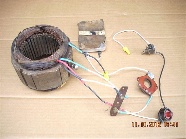
Hi all I have a Dunlap 1/3 Hp Model 115.5454 split phase motor that I need help with connecting the internal wiring. This is the same motor that Franklee restored in late 2015. There is a terminal block in the end bell housing that has two places to attach the ring terminals. There are 5 leads coming from the motor and are shown in the picture. One is from the neutral line and contains the thermal reset switch, one is from the centrifugal switch, 2 are from the stator and connected hot lead and 1 is from the stator and connected to the centrifugal switch. I think that the two from the stator and centrif switch tie together and that leaves the other two. When assembled in this way there is about 4.5 ohms across the input leads. Any advice would be appreciated.
Thanks,
Jim
Dunlap motor leads.jpg
 
To avoid these ads, REGISTER NOW!

Larryjones

Well-known member
Joined
Oct 11, 2015
Messages
494
Location
WV
Your motor is bi-directional and I think the directions are on the name plate which may give you a clue as to where each wire goes. Also I would expect the power leads to be black and white.
 
OP
J

JGHannoosh

Member
Joined
Mar 20, 2017
Messages
6
Thanks Larry. No info on the name plate. Am still trying to figure out which internal wire with ring connector goes where. Am not sure I've got it right.
 
OP
J

JGHannoosh

Member
Joined
Mar 20, 2017
Messages
6
Hi all Thanks for the many suggestions. The best lead I've found is this picture on Vintage Machinery.
15296-C.jpg


It shows how to wire the motor. I think I've got it figured out and will send the diagrams and pix once assembled and running. The thermal reset switch isn't the best and I'd like to replace it but am not finding one yet online
 

kujinn

Member
Joined
Apr 6, 2024
Messages
5
Did you figure this out? I'm trying to rebuild the same motor for my table saw this weekend. Any help you've got would be appreciated!
 

FrankLee

Well-known member
Joined
Sep 13, 2010
Messages
3,578
Location
seMI, 48317
Did you figure this out? I'm trying to rebuild the same motor for my table saw this weekend. Any help you've got would be appreciated!
Please post some photos of the current state of your motor and the motor data plate.
 

kujinn

Member
Joined
Apr 6, 2024
Messages
5
I have replicated the multimeter measurements from this thread: https://www.garagejournal.com/forum...l-115-5454-split-phase-electric-motor.435340/

I think I need to wire up the main loop to AC power gated by the thermal shutoff with the startup loop also gated by the centripetal switch. I just don't know how to determine the polarity of each loop or how to get 2 loops out of 5 wire ends.

edit: I also don't know if it's bad forum etiquette to revive an old post, or if I should just be making my own new one.
 

Attachments

  • 20240406_130132.jpg
    20240406_130132.jpg
    659.1 KB · Views: 31
  • 20240406_130140.jpg
    20240406_130140.jpg
    357.5 KB · Views: 25
  • 20240406_171649.jpg
    20240406_171649.jpg
    567.7 KB · Views: 24
  • 20240406_171659.jpg
    20240406_171659.jpg
    703.3 KB · Views: 29
To avoid these ads, REGISTER NOW!

FrankLee

Well-known member
Joined
Sep 13, 2010
Messages
3,578
Location
seMI, 48317
I could not find any photo evidence that I had a Dunlap 115.5454 motor in 2015 as stated in the first post of this thread. I did have a Dunlap 115.7448. These are the only relevant photos I have and they likely won't help much.
IMG_0302.JPG IMG_0303.JPG
I may have some other pictures that may help, but I just have to find them or take new ones.
 

FrankLee

Well-known member
Joined
Sep 13, 2010
Messages
3,578
Location
seMI, 48317
This is the wiring I cut from an old fubar Companion cap-start motor. This may help if your wire colors match up.

The wires in each zip tie bundle were relatively close together on the stator when I cut them.
 

Attachments

  • IMG_3935c.JPG
    IMG_3935c.JPG
    654.7 KB · Views: 27
  • IMG_3937.JPG
    IMG_3937.JPG
    666.7 KB · Views: 24
  • IMG_3934.JPG
    IMG_3934.JPG
    704.3 KB · Views: 23
  • IMG_3933.JPG
    IMG_3933.JPG
    714.7 KB · Views: 27
  • IMG_3932.JPG
    IMG_3932.JPG
    866.2 KB · Views: 28
Last edited:

kujinn

Member
Joined
Apr 6, 2024
Messages
5
I'm not having much success with the colors. There's one clearly black wire, but the rest are all very sawdust-ey and I'm afraid of damaging them during a concerted cleaning effort.
 

Just a dude

New member
Joined
Feb 14, 2024
Messages
3
I'm working on this same motor. I made the rookie mistake of not taking good notes and pics when I took it apart. I think I have the wires figured out EXCEPT where the other button reset wire goes.

Here are the pics I did take. Maybe these will help someone.115.5454 b.jpg115.5454 c.jpg115.5454 d.jpg115.5454 e.jpg
 

Attachments

  • 115.5454 a.jpg
    115.5454 a.jpg
    578.6 KB · Views: 19

FrankLee

Well-known member
Joined
Sep 13, 2010
Messages
3,578
Location
seMI, 48317
I believe one wire from thermal switch goes to the ON-OFF switch, if equipped; otherwise to the cord.
 

Just a dude

New member
Joined
Feb 14, 2024
Messages
3
Ok. So before I wire something wrong and fry some part of the motor, this is how I'm planning to wire it up. I looked at the diagram on a thread on Hobby Machinist. There's another diagram showing where wires connect. From those 2 diagrams and reading this thread and others, ... this is what I've come up with.

Thanks for helping a confused dude.

My understanding of how it should be wired. I understand that to reverse the motor direction, the connections from the outlet can be switched.
1730769473888.png

The ohms diagram:
1730768244137.png

Wiring Diagram from a thread I don't remember where: The "terminated near motor switch location isn't very clear to me.
1730768049028.png

My other question is what do each of the wires do? What part of the stator do they operate?
Again, thank you
 

mike61

New member
Joined
Jan 25, 2026
Messages
4
I have the same motor, trying to rewire, would below be correct? Some pic of what I have below
Wire 1 to ?
Wire 2 to Left terminal
Wire 3 to CS
Wire 4 to Left terminal
Wire 5 to right terminal
Wire from CS to TRS
wire from TRS to Right terminal
 

Attachments

  • IMG_2866.JPG
    IMG_2866.JPG
    950.8 KB · Views: 3
  • IMG_2865.JPG
    IMG_2865.JPG
    1,015.4 KB · Views: 3
  • IMG_2864.JPG
    IMG_2864.JPG
    1.2 MB · Views: 4
To avoid these ads, REGISTER NOW!
Top Bottom