I see I'm a bit late to the party here.... but I will add in some things... FYI earthing is not the correct term for any of this...
Forgive the question. I'm not an electrician, but know enough to get in trouble. I have a sub panel bolted directly to my original panel. This sub panel doesn't seem to have any of it's circuits grounded. The main panel does have everything grounded. In the main panel I only see neutral busses. I also see the case has a strap from the neutral bus to it. There is a neutral wire from the main panel to the sub panel. There is continuity between the neutral on the main and sub panel neutrals as well as neutral and the cases on each. The sub panel also has a lug from the neutral bus bar to the case.
The circuits are grounded in the subpanel but its incorrect. The EGCs are going to the neutral bar and they should be going to a separate ground bar.
Also the neutral bar in the sub should be isolated meaning that bonding strip needs to be removed.
I'm trying to better grasp the grounding concept here but also would like a layments description as to why the main panel sees ground yet the other doesn't. For reference I was looking at one outlet that tests correctly and is attached directly on the main box there are two wires (One hot and one neutral). I assume the box is being used for he ground. If this was the case I'd assume that the sub box would also be grounded since there is continuity between the two boxes.
The two GCFI breakers in the sub panel I have added while doing some basement work and when testing the outlets I noticed no ground on my outlets or the other existing circuit I tested. Everything works (Except having no ground so I cannot test the GCFI function).
A GFCI does NOT need to be connected to an EGC/ground in order to function or test. A GFCI does not even reference the ground wire when in operation.
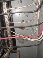
I'm clearly failing to understand grounding here. I've included a few pics. I have 2 large hot wires coming in and the one on the right I believe is a ground or neutral? The neutral bus bars on the left/right of the main panel are connected together and the top left goes to another sub panel in my garage as well as my bathroom addition that were done at the same time before I moved in. I included a few pics
Dave
Equipment grounding conductors work like this. The bare wire from the PoCo is neutral not ground as the PoCo does not distribute a ground to services.
The neutral bond in the main panel is what establishes the low impedance ground fault pathway. When an ungrounded conductor touches a bonded/grounded chassis, frame, conduit, panel etc., the EGC provides a low impedance fault current pathway allowing high amperage fault currents to make there way back to the neutral/ground bond in the main panel. These high energy currents cause the magnetic trip mechanism in the breaker feeding the offending circuit to trip, opening the ungrounded conductors and thus clear the fault current.
Without the neutral to ground bond in the main service panel, there would be no way for breakers to clear fault current.
Now you only want this bond in the main service panel because if you have it in subpanels and the neutral fails, then you can have dangerous shock potential and neutral current returning to the main service panel or transformer on unintended pathways such as a person touching the frame of the panel while standing on concrete or touching a ground pipe.
See this is what I don't understand fully.
1. I don't see any grounding source, rod, pipe or otherwise to main panel. I'm guessing this is the neutral wire into the panel? I do know there is one grounding rod by my electrical meter outside but I think it's actually to ground my cable/coax feed into the house.
Now grounding electrodes are an entirely different animal. Sberry already touched on this a bit earlier.
Grounding electrodes are for limiting step potential and voltage to earth as well as shunting lightning to earth. They DO NOT provide a low impedance fault current pathway.
Original code back in the day called for 1 ground rod and a water line bond if it met the requirements to be an electrode.
Nowadays, 2 rods are required or 1 UFER and nothing else.
If you have a ground rod for the cable service, it needs to be connected/bonded to the grounding electrode system for the electrical service.
2. Can you explain why the ground source for the sub panel grounding bar is separate from (but sourced from) the same neutral bus bar on main panel? Would the fact my neutral and ground busses are not separate on the sub panel be why I see no ground to outlets? I am confused how that could be possible as I have continuity from what the source of that ground bus would be (the neutral bus of the main panel) and the neutral of my panel.
your subpanel is wired incorrectly. It should have 4 wires- 4 #10s or 3 #10s if connected via metal conduit.
There needs a ground bar and neutral bar needs to be isolated.
3. The person who installed this sub panel years ago did bond the neutral bus to the case. This case is physically bolted to the main pain and there is continuity, what problems will this create?
Thank you
Dave
shock potential on the chassis if your neutral wire fails.
The pic is a bit deceptive as the sub panel is fed by I believe 10ga(Haven't looked that closely but perhaps you are right now that I look closer comparing the wires) but the 220 breaker on main panel second down, top right is what feeds them. I will check that later and replace those feeds if they are 12awg. Yes they did run a black neutral to sub which I'll also fix, should that be the same gauge as the power feeds? The sub panel is "mostly" EMT but in my unincorporated area away from the city (I called the inspector to verify) NM is acceptable in a basement and doesn't even require GCFI if the basement isn't fully finished. I added the NM for my outlets in basement and the lights i put in. I went ahead and added GCFI breakers for my two 20A circuits (Used 12/2 NM and also ran the grounds as you can see in that sub panel) as a precaution since there is a sump down here which "could" fail. If the water ever gets to outlet height though I'm moving out!
I want to get a proper ground down here and it seems (as you also say) to do this I need to unbond the neutral from the case and run a separate earth. I still don't know how that'd get the circuit a proper ground though since the non GCFI breakers I have wouldn't reference that earth would they since the neutrals would still go to the neutral bus and only my GCFI breakers would have a wire going from them to the ground bus bar.
yes the neutral needs to be white insulated and should be same size as ungrounded conductors.
If the panels are connected with metal conduit, then you do not need to run a separate ground wire but you do need to add a ground bar, move the grounds to it off of the neutral bar, and unbond the neutral bar.
Now dont go confusing GFCIs in the mix. has nothing to do with the issues in your subpanel.
Well, I'm a bit embarrassed now. While my thought process was sound my testing equipment, not so much. After I noticed no ground on one of my code required child proof outlets I tested in an older one. Turns out the ground tab on my tester was pushed in a hair. Enough to contact the non child protected outlet but not my new outlets. After pulling that ground tab out all is well. With that said a few things.
1. The feeds are 10AWG, should I increase this to 8AWG or smaller w/ the given breaker config (1 50A 220), 4 20A, 2 15A?
2. As far as the neutral, can I wrap some white electrical tape around the neutral feeds at the lug or is this even something I should worry about?
3. Should I still unbond the neutral bus bar of the sub-panel?
4. I read that I "should" be running a ground rod (2 actually) for the sub panel. Is this overkill?
5. Is the neutral wire into the main panel actually from a ground rod?
1. The breaker feeding the subpanel is 240v 30a so no point in increasing the feeder wire size. However, depending on the diversity of the loads in the subpanel, you may need to. Obviously you will not get 50a for that 50a 240 circuit you have running off of the subpanel.
Can you list the loads in the subpanel.
2. If you want to abide by code, then no you cant just wrap some white tape around it. that is only allowed for conductors size 4 and larger.
3. YES! most definitely.
4. NOPE you do not need ground rods for the subpanel since its in the same structure as the main. however the main does need to have grounding electrodes connected to the neutral bus bar along with a bond to metal water line and gas line if you have them.
Some PoCos allowing ground rod connections to be made at the meter pan so I would check outside first.
5. The neutral wire would most definitely NOT be coming from a ground rod. It would be coming from the neutral lug in your meter pan. However as i said above, its possible the neutral lug in your meter pan has a ground rod terminated to it.
6. Have i wired my GFCI breakers properly?
7. Is using a square DGFI breaker really going to bite me in the ***? Is it standard practice to use the same brand as the box? It seems ITE and Siemens are one in the same? Can Siemens breakers be used moving forward?
Attached a few more pics of the sub panel config. for reference on my GFI wiring. I have the bottom area going to the neutral bus bar (No ground bar on either box), i have the neutral going to neutra of the outlet and then the hot to the hot of the outlet. The bare copper wire also goes to the neutral bus bar.
Thanks again guys
Dave
6. The GFCI breaker neutral pigtail needs to go to the neutral bar in the panel and the neutral from the circuit needs to go to the breaker.
7. yes you should use the same brand and model of breaker listed for the panel. In your case ITE or siemens breakers only. Siemens is the successor to ITE.