To avoid these ads, REGISTER NOW!

Eastwood Buff Motor Wiring HELP

Bigezee

Member
Joined
Feb 9, 2015
Messages
14
I need some desperate help rewiring my new Buffing motor. Long story short the motor vibrated loose from the base and pulled all the wires off. I tried to hook it back up and the switch burned up and now I have nothing but what is in the picture. I tried to get help at the Eastwood forums but they were no help there. So now I am stuck with a new motor that I can't use. Can someone please help me figure out how to rewire this back up as I have a lot of parts to clean up! I have a Fluke meter I can use to test with.

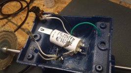
As you can see in the pic of the wiring, the black and white at the top come off the power cord and go into the on/off switch(burned up but connections still there). There are 2 white and 2 black coming from inside the motor. I only have 4 connections to hook up, 2 on the switch and 2 on the capacitor, but don't want to do any more damage. Any help would be greatly appreciated.
 

Attachments

  • 20150626_205119.jpg
    20150626_205119.jpg
    149.7 KB · Views: 20
  • 20150626_205210.jpg
    20150626_205210.jpg
    146.3 KB · Views: 26
  • 20150626_210241.jpg
    20150626_210241.jpg
    151.4 KB · Views: 31
To avoid these ads, REGISTER NOW!

6t7gto

Well-known member
Joined
Dec 6, 2005
Messages
522
Location
bedford,ohio
Where did the switch mount?
The length of the wires should give you a hint where they were connected .
 
OP
B

Bigezee

Member
Joined
Feb 9, 2015
Messages
14
Thanks for the response. Switch was at the bottom of the picture but already tried that . they are all the same length and could go anywhere.
 
OP
B

Bigezee

Member
Joined
Feb 9, 2015
Messages
14
Would be happy for just a general schematic of a basic capacitor start bench grinder.
 
To avoid these ads, REGISTER NOW!

MTW

Well-known member
Joined
Aug 6, 2013
Messages
294
Location
SE Michigan
Use that fluke meter and measure the resistance of the wire pairs (black, white). The pair with the lowest resistance will be the line volt side. The pair with the higher resistance will be the capacitor pair.

The line volt pair (low resistance) will be reading the running winding. The capacitor pair will be reading the run and start winding in series (higher resistance)

Be sure to set your meter on the lowest Ω scale, and keep the wiring isolated.

CapacitorRunMotor.jpg

Whats up with that gob of silicone? Wouldn't a dab of lock-tite on the screws suffice?

MTW Ω
 
OP
B

Bigezee

Member
Joined
Feb 9, 2015
Messages
14
Thanks for your reply! Will use your help and try to get it hooked up. At least you have given me something to try...thanks!!

Whats up with that gob of silicone? Wouldn't a dab of lock-tite on the screws suffice?

lol. I actually did put loctite on and lo and behold the small fine thread screw was stripped out to begin with. Gotta love this cheap Chinese metal. I got pissed and made sure the base wasn't coming off again after I got it wired back up. Really only thing I could do. Just went overboard..!!
 

justsam

Well-known member
Joined
Aug 20, 2010
Messages
1,267
Location
Penngrove, California
Careful with the use of RTV Silicon as a potting agent. Many of them release acetic acid during curing and will pretty much destroy electrical connections, in short order, especially if in an enclosed space. If it smells like vinegar during curing you will have a problem.
 
OP
B

Bigezee

Member
Joined
Feb 9, 2015
Messages
14
Got it working!! Thanks to MTW for his help. I did exactly like he said and it worked first time! This buffer has been down for months until now!! Thanks again.

Careful with the use of RTV Silicon as a potting agent.

Not sure what a potting agent is but I just used the silicone to mount the base to the motor. It has been open and drying for over a week now so no enclosed off-gassing.
 
To avoid these ads, REGISTER NOW!
Top Bottom