To avoid these ads, REGISTER NOW!

Electric Motor from the 50´s , info please

MBfreak

MEMBER EMERITUS
Joined
Dec 10, 2010
Messages
2,301
Location
Linkoping , Sweden
Hi guys.
I am involved in the resto of FUTURLINER # 8 here in Sweden, doing the electrical stuff.
I am looking for any and all info, experience, doc or general info on a
MASTER GEARHEAD MOTOR, 110 V 1/2 HP manufactured by " The Master Electric Company, Dayton , O(hio?) , USA. I think it is made around 1950.
It is incredibly well built, all insulation is as new (> 50 MegOhms at 500 V) and gears, bearings is in almost as new condition. However, since I am a firm believer in restoration before test, the motor will be technicaly rebuilt and cosmetically made to look as new.

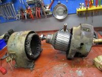
It is a strange beast, the 1 phase staor winding is connected in a delta with three wires ( fwd, rev and common) and the rotor is a commutator rotor where two brushes 180 deg apart are connected to each other ( and ground) I understand how it works , but have never seen a 1 phase reversible AC motor of that design before
The pic shows the stator and rotor separated.

This particular motor drives the pantograph that raises the lighting fin. Immensly cool! There are 5 more! And a 10 kVA generator weighing in at 650 kilos!

Please guys, any info at all is most welcome.

Best regards

Ola
 

Attachments

  • Stator and rotor.JPG
    Stator and rotor.JPG
    45.7 KB · Views: 95
To avoid these ads, REGISTER NOW!

nehog

Well-known member
Joined
Jan 2, 2010
Messages
7,935
Location
Jaffrey, NH
Repulsion start motor perhaps, if the brushes are shorted to each other. Was common back then, but no longer used (that I know of). I have an old one sitting under my workbench which IIRC came off my lathe.
 
OP
M

MBfreak

MEMBER EMERITUS
Joined
Dec 10, 2010
Messages
2,301
Location
Linkoping , Sweden
Hi Steve.
Thansk for your input.

I think this design is called , in US parlance, a repulsion motor. It will only run on AC, as opposed to a universal motor ( series motor in Swenglish) that can run on AC or DC. In the repulsion motor, the rotor is only magnetically coupled to the stator field. At slow turning a rotor voltage is is induced which is closed in a current loop thru the two brushes. This gives a good starting torque. Once it comes close to synchronuos speed ( 0,8 pu?) a centrifugal mechanism moves a short circuiting ring that connects all rotor bars together, making it a sqirrel cage AC motor at .
A design that I have only read about way back, never even seen before!

Ola
 

Greatbear

Well-known member
Joined
Jan 17, 2008
Messages
1,702
Location
Columbia/Fulton, MD
This looks like a dual stator universal motor used in reversing applications. There are basically two stator windings with the rotor connected between, whichever wire you apply power to determines the polarity of the stator with regards to the rotor. The common stays put, of course. This method is used to simplify directional control wiring, so in this case you only need two normally open momentary switches, rated for the motor current, to make a working circuit. The disadvantage of this style of motor is some inefficiency from using the "idle" stator winding to complete the rotor circuit. The way around this is to use double pole double throw momentary switching and individual feeds for the stator and rotor, but that raises complexity and the chance for breakdown.

As others have said, I am also interested in seeing this restoration in progress!
 
OP
M

MBfreak

MEMBER EMERITUS
Joined
Dec 10, 2010
Messages
2,301
Location
Linkoping , Sweden
Hi Guys.

Thanks for answers, nihog is right on the money.

It is a single-phase reluctance motor. There are two stator windings, in order to make the motor reversible. The rotor is ONLY magnetically coupled . At low RPM´s the two carbon brushes that are sitting 180 deg apart and connected to each other establishes a "stationary " field in order to get a good starting torque
Once rpm goes up to appr 650 ( 6 pole 60 hz is 1200 sync speed), a really nifty rotor short circuit contraption takes over which connects all commutator bars together ( yes, i spun the rotor in a lathe and watched it work!) , thus creating a normal squirrel cage 1 phase motor.

I am happy to say that I now have the theory worked out. This is always a must for me. I have to understand in considerable detail how things work, be it a cold chisel or a piece of software.

What I now look for is manufacturers pamphlets, drawings or anything at all from the company who made this motor, guess end of forties or even earlier.

The Master Electric Co, Dayton, O, USA.

The FUTURLINER itself is taking shape, but presentlyI am not up to speed on that, have enough to do with electrics!

Ola
 
To avoid these ads, REGISTER NOW!

ears

Well-known member
Joined
Mar 23, 2008
Messages
943
Location
lorton VA
Master being a fairly common word, you may have better luck googling "master speedranger". Speedranger being the variable speed drive that was likely on the business end of that motor. There is quite a bit of info on practical machinist. I just went through this a while back and found lots of info old ads etc, there is quite a bit out there.
 

JBurgess

Well-known member
Joined
Mar 1, 2008
Messages
372
Location
Arizona
Here's some illistrations of that type of motor and wiring.

Pics088.jpg


Pics087.jpg
 
OP
M

MBfreak

MEMBER EMERITUS
Joined
Dec 10, 2010
Messages
2,301
Location
Linkoping , Sweden
Hi.

The book is now ordered!

Thanks a lot to all.

I have had a closer look at the intgrated commutator shorting out mechanism. Amazingly clever design. If you do not know it is there, you are likelyto miss it!

Again, thanks guys .

Ola
 
To avoid these ads, REGISTER NOW!
Top Bottom