To avoid these ads, REGISTER NOW!

Electric Motor Wiring

RHJO51

Well-known member
Joined
Feb 27, 2015
Messages
242
Location
Red Hook, NY 12571
Hey Folks, I'm looking to use an old electric motor for a small drill press I'm putting together. I don't know squat about electric motor wiring so looking for some help. With a test cord, I'm not getting any response from the two round terminals labeled 1 & 2, but the motor spins using the spade terminals labeled 4 & 5. No access cover or wiring diagram. Can some one tell me the correct terminals to use for 115v? I'll add a ground wire. Thanks - Jim
 

Attachments

  • IMG_2948.JPG
    IMG_2948.JPG
    289 KB · Views: 77
  • IMG_2949.JPG
    IMG_2949.JPG
    258.9 KB · Views: 74
To avoid these ads, REGISTER NOW!

Cruzan80

Well-known member
Joined
Jul 22, 2015
Messages
4,227
Location
Denver, CO
The general idea is that there are two sets of run windings tied together (1&3 and 2&4) and you run your hot/neutral to one set (say 1-2). There is usually a capacitor in a start winding (T5-T8) that is disconnected once up to speed.

A multimeter will be able to tell you what has continuity (pathway) from terminal to another. The issue you are having is there is more wiring going on underneath there which you cannot see. Sending electricity thru the start windings will burn the motor up quickly.
 
OP
R

RHJO51

Well-known member
Joined
Feb 27, 2015
Messages
242
Location
Red Hook, NY 12571
Thanks for the reply. So I tested it and I have continuity between the two spade terminals - 4&5, but not the threaded terminals - 1&2. So to be clear, I should be using the two spade terminals which have continuity? Thanks for your help.
 

Cruzan80

Well-known member
Joined
Jul 22, 2015
Messages
4,227
Location
Denver, CO
Did you test between 1 and (4 or 5)? Same for 2. You should get two different sets of terminals, reading as showing continuity.
 
OP
R

RHJO51

Well-known member
Joined
Feb 27, 2015
Messages
242
Location
Red Hook, NY 12571
I tested between 1 &4 or 5 and 2 and 4 or 5 and there is no continuity between any of those connections - only between the two spade terminals - 4 & 5. Should I be using 4 & 5 for my power connection? Thanks - Jim
 
Last edited:
OP
R

RHJO51

Well-known member
Joined
Feb 27, 2015
Messages
242
Location
Red Hook, NY 12571
Anybody? Is there a jumper missing or can I hook up the power leads to 4&5 where I have continuity? I don't want to damage the motor but I need this motor. Thoughts?
 

Cruzan80

Well-known member
Joined
Jul 22, 2015
Messages
4,227
Location
Denver, CO
I am thinking there is a jumper missing. Cracking open the endbell to see the inside of that aprt would also be helpful, but understand if you are reluctant to do so.

Sorry, this has been a steing of crazy for me this week. Otherwise, I wiuld find somethjng close and confirm wiring.on a known good motor.
 
To avoid these ads, REGISTER NOW!
OP
R

RHJO51

Well-known member
Joined
Feb 27, 2015
Messages
242
Location
Red Hook, NY 12571
I'm looking for another motor somewhere but it irks me not getting this motor working correctly. I popped off the end bell to see what's what underneath. Seems good, nothing broken of missing best I can tell. The two spade clips where I was getting continuity are the two wires to the right of the pictures and in the close up. So, are the two spade connectors correct for power cord hook up? or am I missing a jumper wire? Or? Thanks for your help.
 

Attachments

  • IMG_2981.JPG
    IMG_2981.JPG
    436 KB · Views: 35
  • IMG_2982.JPG
    IMG_2982.JPG
    360 KB · Views: 30
  • IMG_2983.JPG
    IMG_2983.JPG
    344.5 KB · Views: 35

Cruzan80

Well-known member
Joined
Jul 22, 2015
Messages
4,227
Location
Denver, CO
That helps a lot. I will point out what terminals control what in about an hr (teaching currently).
 

Cruzan80

Well-known member
Joined
Jul 22, 2015
Messages
4,227
Location
Denver, CO
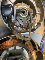
So I put together a quick A-E Listing, so you can match it up with the other side easiest. Short answer, power to A and C should result in it spinning

The A and B are connected by the centrifugal switch, which is used to connect and disconnect the start windings. Once it starts spinning up, the weights get pulled in, and B disconnects, taking the start windings out before they can burn up. (Start windings are the thinner darker coils)

C gives power to the thermal overload, which then looks to branch down on the left side into both the start and run windings. A connects to one end of the run winding. One wire on the bottom of the thermal overload is the other end. (Run windings are the brighter copper thicker coils).

I would clean up the tabs at the end of A and D, and make sure the contact between A and B is clean. I would also make sure the springs on the rotor are bending easily enough for the weight to move back/forth.

You should be able to get continuity between C and one of the bottom wires off the thermal reset. There should be continuity between B and the other wire from the reset. If not, that is the reason it is not working (the overload disconnected inside, and either needs to be reset, or replaced if broken).

Edit: Attaching the picture helps...
 

Attachments

  • Inside Labelled.jpg
    Inside Labelled.jpg
    531.5 KB · Views: 29

Cruzan80

Well-known member
Joined
Jul 22, 2015
Messages
4,227
Location
Denver, CO
The reason this threw me for a loop is the numbering convention. Not sure what exactly posts 1 and 2 are supposed to do in this motor at all, but usually we connect T1/T4 and loop T5 in thru a relay or cent. switch (internal motor wire labelling). Looking closer at the initial picture, I wonder if the dark line by the 4 terminal is supposed to be a 1, which would line up with the above!
 
OP
R

RHJO51

Well-known member
Joined
Feb 27, 2015
Messages
242
Location
Red Hook, NY 12571
Many thanks Cruzan80! I’ll give it a try tomorrow when I’m back in the shop. I appreciate you taking the time and effort to help me. Thanks again. - Jim
 
OP
R

RHJO51

Well-known member
Joined
Feb 27, 2015
Messages
242
Location
Red Hook, NY 12571
I put the motor together and wired it up. Worked great, thanks a lot! it’s on the DP and working fine. Thanks again for the help, I appreciate it.

I hate to ask, but I’ve got one more motor that I need some help on, a nice Craftsman 1/2 hp. Seems dead. I’ll check the continuity between the terminals and pull the end cap. Hopefully you can tell me the correct terminals to use for the power cord.

thank you- Jim
 

Cruzan80

Well-known member
Joined
Jul 22, 2015
Messages
4,227
Location
Denver, CO
Happy to help. Hopefully the capacitor on the CM isnt dead as they are no longer made in that form factor.
 
To avoid these ads, REGISTER NOW!
Top Bottom