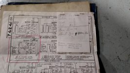
OK so I got this motor and switch that were together at one time...Never saw it together but I got all this documentation on how it should be wired and I thought I could figure it out but now I have confused myelf with so much documentation...Anyone please help me out!!

You are using an out of date browser. It may not display this or other websites correctly.
You should upgrade or use an alternative browser.
You should upgrade or use an alternative browser.
Electric motor with forward reverse switch
- Thread starter phoenix5x
- Start date

LS6 Tommy
Well-known member
Many single phase motors are reversible. We need better photos of the diagrams...
Tommy
Tommy


Dagny
Well-known member
how many terminals are on the switch 4 or 6 or 9?
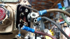
Honestly don't know...never opened the box..This cable comes out with the 4 wires and another cable that plugs into the outlet. The box itself just has a forward and reverse lever on the outside..hope this pic helps shows the box with the lever

Sent from my XT1254 using Tapatalk
Sent from my XT1254 using Tapatalk
Dagny
Well-known member
You have a drum type switch but your diagrams are for a toggle switch under the drum switch cover should be more diagrams although usually incorrect diagrams because they don't take the thermal cutout into consideration . There should be 5 wires between switch and motor. Hot going to the cutout then back to drum switch. then black and red are start winding and last the other run winding.
I will pull the switch cover off tomorrow and see what I have in there as far as diagrams and get some pics...thanks for the info thus far...wonder how this worked then if all they did was clip the wires off...maybe it just had forward working?
Sent from my XT1254 using Tapatalk
Sent from my XT1254 using Tapatalk
Last edited:
OK so here is the inside of the drum switch looks like a 9 terminal as well as what was inside the cover but no wiring diagrams..I will see if I can find one with the info on the inside of the drum switch..maybe somebody out there got some info...


Sent from my XT1254 using Tapatalk
Sent from my XT1254 using Tapatalk

Here is how they are usually wired....your upper six terminals. Check your terminals (less all the wiring) against the upper diagram with a test light to verify the switch action. If not exactly the same, move around to find that configuration. The switch needs to move to the center "off" position to allow the motor to stop and have the start winding switch (centrifugal) close, before the motor direction can be changed.
Attachments


Last edited:
Thanx...I will plug this in and put my test light on the exposed terminals and see how the switch reacts..if that draws more questions than conclusions I will post em up...appreciate the info guys
Sent from my XT1254 using Tapatalk
Sent from my XT1254 using Tapatalk
Get yourself a powered continuity tester like this...great for switch and fuse testing, etc.
http://www.amazon.com/dp/B00027FOPC/?tag=atomicindus08-20
http://www.amazon.com/dp/B00027FOPC/?tag=atomicindus08-20
Like this one...
http://www.amazon.com/gp/aw/d/B003U...-08d5-5f02-b478-97dfe1c148d0&pf_rd_i=15707391
Sent from my XT1254 using Tapatalk
http://www.amazon.com/gp/aw/d/B003U...-08d5-5f02-b478-97dfe1c148d0&pf_rd_i=15707391
Sent from my XT1254 using Tapatalk
wyliesdiesels
Well-known member
Get yourself a powered continuity tester like this...great for switch and fuse testing, etc.
http://www.amazon.com/dp/B00027FOPC/?tag=atomicindus08-20
Boy thats the cheapest knock off tool Ive ever seen.
If u go to sperry's site, that one isnt even on there.
Looks like a fake knock off to me!
Yeah they just a cheap o tool I have had for a long time...I wouldn't call it a professional tool..but yeah you have to have a power source for it to work..basically just checks the flow of power...also have one if these...
https://jet.com/product/detail/e21d...29a553a5fb76&gclid=CM-swYyypckCFRCNaQoddSYCMQ
Sent from my XT1254 using Tapatalk
https://jet.com/product/detail/e21d...29a553a5fb76&gclid=CM-swYyypckCFRCNaQoddSYCMQ
Sent from my XT1254 using Tapatalk
Boy thats the cheapest knock off tool Ive ever seen.
If u go to sperry's site, that one isnt even on there.
Looks like a fake knock off to me!
No knock off there, a genuine Sperry. But, it is a discontinued model, with apparently lots of stock still out there. I got mine at Princess Auto and they have a few left on the shelf too!!