To avoid these ads, REGISTER NOW!

Engine Stand Modification – Opinions?

MTRD3

Active member
Joined
Dec 21, 2012
Messages
38
Location
Munich / Toronto
Hi guys, so I picked up one of those budget engine stands recently and was putting it together last night when something kinda irked me. Funniest part is, the printed instructions that were in the packaging illustrated the assembly exactly the way I’m considering altering the parts to make it (even the hardware checklist had the parts I would need to have it exactly as I plan to modify it and as the instructions displayed it) but those specific pieces of hardware were obviously missing because the final product that was in front of me did away with them and instead used a different (seemingly unrefined) method of fixation.

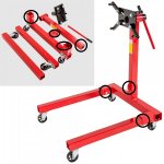
As you can see in the pics below, the legs of the stand are fixed into the cross member of the frame by advancing a bolt through a threaded hole to apply counter force to the metal legs and press them against the opposing side metal of the frame like a wedge. What I had expected were matching holes in the legs and frame on both sides which would accept a through bolt secured with a washer and nut. Seems like a much better way of fastening something (IMO). Same goes for the part of the frame that holds the vertical post which the engine mounting plate is attached to.

Don’t get me wrong, my expectations at this price point were managed and I’m not unhappy with the product I received for the price, but I am thinking of reeming the necessary wholes needed to fix all three points with through bolts, a washer and a nut. Do you guys think this is an unnecessary undertaking? Are there any negative effects that can be caused by drilling these? (I have no idea here but the thought of structural integrity of the material did come into my mind when considering drilling the additional holes in the parts).

LMK Thanks!
 

Attachments

  • TecTake 1.jpg
    TecTake 1.jpg
    65.9 KB · Views: 50
  • TecTake 2.jpg
    TecTake 2.jpg
    73.6 KB · Views: 44
  • TecTake 3.jpg
    TecTake 3.jpg
    47.8 KB · Views: 47
To avoid these ads, REGISTER NOW!

David Paul

Well-known member
Joined
Jul 11, 2014
Messages
677
Location
Western New Jersey
I like your idea, and in fact have seen it used on engine stands. I would make the modifications you have in mind. I can't see any down fall to doing it. I would at least do the legs. Can you imagine moving the stand with an engine on it and in the unlikely event one pull out? Wouldn't be pretty. The vertical post will stay put with the weight of the engine but I would do it any way so that all are the same. I'm weird like that.....
 

David Paul

Well-known member
Joined
Jul 11, 2014
Messages
677
Location
Western New Jersey
Oh, and if you do a lot of assembling/ disassembling of the stand, us a sheer pin type assembly with a retaining clip on the other end (can't recall the proper name right now) rather then a bolt and washer. Would save some time and effort. I would also drill the holes with weight on the stand. That way the weight will be on the fram structure and not the bolt/pin.
 
Last edited:
OP
M

MTRD3

Active member
Joined
Dec 21, 2012
Messages
38
Location
Munich / Toronto
Can you imagine moving the stand with an engine on it and in the unlikely event one pull out? Wouldn't be pretty. The vertical post will stay put with the weight of the engine but I would do it any way so that all are the same. I'm weird like that.....

My thoughts exactly... good to know I wasn't over analyzing here.

Oh, and if you do a lot of assembling/ disassembling of the stand, us a sheer pin type assembly with a retaining clip on the other end (can't recall the proper name right now) rather then a bolt and washer. Would save some time and effort. I would also drill the holes with weight on the stand. That way the weight will be on the fram structure and not the bolt/pin.

Sounds like you mean a sheer & cotter pin setup. I'm not completely sure I understand what you mean in terms of drilling with weight on the stand.. I actually haven't put it together yet (after noting these things I stopped and thought I'd go to the hardware store this evening and get the few additional things I need to make my desired modifications) so it's in pieces and I planned to drill each piece while it was apart.
That being said, do you mean something to the effect of drilling it while an engine was mounted so that the vertical post was under the expected "downward load" and the ensuing hole that would be drilled would be positioned so that the bolt or pin that goes through it would not bear any weight when an engine that was first mounted pressed the vertical post down with its weight? Does that even occur? On the legs I can't imagine this plays a role.. I could easily be wrong though lol.
 

the gypsy

Well-known member
Joined
Mar 13, 2013
Messages
1,780
Location
Montreal, Quebec, Canada
the bolt that wedges the extended legs against the other piece is most probably there because the pieces are not tight for easy insertion. For this reason I would not remove but I would make another hole through and through and put in that Sheer pin with cotter pin. This way you remove the pins loosen the wedging bolt and out it comes.
 

Jagmandave

Well-known member
Joined
Nov 6, 2011
Messages
6,299
Location
Overland Park, Ks.
If you bolt it thru chances are good that as you tighten the bolts you'll compress the tubing - asking for failure unless you weld a tube inside the inner piece to accept the compression force of the bolt.

I also would not use a pin and cotter, you then transfer all the forces to the edges of the holes and they'll wallow out, making it loose and sloppy unless there is substantial amount of the inner tube inside the outer one and the pin is only for location, as on the HF engine hoists.

If you don't intend to disassemble it again, you could run a good weld bead where the joints are, but I'd leave it as built.
 

Thumper68

Well-known member
Joined
May 16, 2013
Messages
5,134
Location
Duluth MN
My guess is that they changed the design for easy of assembly/disassembly, most guys that are buying the cheaper stands have small shops and need to tear it down for storage while not in use just like the engine hoists are desgined to fold for storage.

I would leave the pinch bolts and drill new holes for a through bolt and weld spacers to prevent crushing of the tube. My piece of mind would over rule the need for easy disassembly.
 
To avoid these ads, REGISTER NOW!

rsanter

Well-known member
Joined
Dec 22, 2007
Messages
18,487
Location
visalia ca
Yes you should
If it was me I would either weld to upright in place or add to the tube of you still want it to come apart. Seems like that piece is a little short for what is supposed to be a "heavy duty" design

Bob
 

the gypsy

Well-known member
Joined
Mar 13, 2013
Messages
1,780
Location
Montreal, Quebec, Canada
Hey Thumper68, I must say great minds think alike. The only difference is you expressed youself with the proper word "pinch bolt". I must say that I agree that welding spacers would make it stronger but wouldn't it be tight making the assembly disassembly a little harder.
 
OP
M

MTRD3

Active member
Joined
Dec 21, 2012
Messages
38
Location
Munich / Toronto
the bolt that wedges the extended legs against the other piece is most probably there because the pieces are not tight for easy insertion. For this reason I would not remove but I would make another hole through and through and put in that Sheer pin with cotter pin. This way you remove the pins loosen the wedging bolt and out it comes.

Eureka! This, along with the other replies, are what I love so much about this site. In a short period of time I got some great insight that helped me notice facets of this construction that I didn't on my own. I just got in and checked the stand and right enough the outer diagonal of the legs is purposefully smaller than the inner of the frame so that they insert easily. Now I'm glad I didn't change the pinch hole, or better said legs & frame, to continue into a through hole and will instead opt for what seems to be the "best of both worlds" solution and add a secondary hole which will be a through hole to accept the sheer & cotter pin setup.

Merci a vous, voisin!

If you bolt it thru chances are good that as you tighten the bolts you'll compress the tubing - asking for failure unless you weld a tube inside the inner piece to accept the compression force of the bolt.

I also would not use a pin and cotter, you then transfer all the forces to the edges of the holes and they'll wallow out, making it loose and sloppy unless there is substantial amount of the inner tube inside the outer one and the pin is only for location, as on the HF engine hoists.

If you don't intend to disassemble it again, you could run a good weld bead where the joints are, but I'd leave it as built.

My intention was to use the bolt or sheer pin as a means of just blocking the inserted piece(s) into the frame in order to not allow for any unforeseen movement. In this case, I hadn't intended to tighten the bolts to the point where they'd compress the metal so shouldn't I be ok with just having them secured in place, occupying the holes as blockers, with the only pressure against the metal being that from the pinch bolt? I noticed in order to tighten the pinch bolt to hold well it leaves a compression mark on the inserted leg (which is fine) but now if I have a through pin/bolt I'll have that secondary feature, which in the event that the pinch bolt loses, stops the parts from separating when moving... or?

Welding is out because I want to be able to disassemble the unit if it's not going to be used for long periods of time.. my work space is confined.

Thanks for the input!

My guess is that they changed the design for easy of assembly/disassembly, most guys that are buying the cheaper stands have small shops and need to tear it down for storage while not in use just like the engine hoists are desgined to fold for storage.

I would leave the pinch bolts and drill new holes for a through bolt and weld spacers to prevent crushing of the tube. My piece of mind would over rule the need for easy disassembly.

That's the new plan :thumbup: minus the welding of spacers. Like I said, I don't intend to exert compression with the through bolt or sheer pin in any way, just lock things in place. Compression will only come from the pinch bolt which complies with how the stand was originally designed.

Thanks! As usual, GJ rocks :beer:
 

stratman977

Well-known member
Joined
Jan 26, 2012
Messages
633
Location
Belle Vernon, PA
In those legs I would just drill another through hole directly behind the pinch bolt. It doesn't have to be a monster bolt as it shouldn't be carrying any load. You don't need to tighten the **** out of it. Its just to keep the legs from pulling out.

On a beam like that the largest stress is on the top and bottom so a reasonable sized hole on the center of the sides wouldn't be detrimental.

The pinch bolt is good to keep the legs nice and tight, otherwise it will be hard to push around cause the leg will flop instead of rolling.

Edit: Looks like you already came to the same solution.
 

ScottsGT

Well-known member
Joined
Jan 1, 2014
Messages
4,883
Location
Lake Wateree, SC
Drill hole in leg so bolt can go through one side. Tighten down. Bolt will work as a pin through the leg so it won't pull out.
 
To avoid these ads, REGISTER NOW!
Top Bottom