To avoid these ads, REGISTER NOW!

EVSE (EV Charger) "Earth Fault" - detecting with a meter?

dcg9381

Well-known member
Joined
Jun 20, 2018
Messages
12,079
Location
Austin, TX
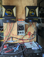
So I'm working on something a little off the main stream. Basically, I'm using large 50V Lithium batteries (6 of them) to power hybrid inverters. The configuration is actually 2 inverters (split phase) that provide power to my "main" panel.

I've got it up and working (prototype, excuse the spaghetti wiring, we're just trying to make it work first), except I have an EV charger that is indicating "Earth Fault".

It does not trigger faults when passing through my grid connection. Definitely faults when not connected to the grid, which it's operating stand alone.

My question is probably pretty simple: How can I detect this fault ("earth fault") on a meter? Am I looking for current between N/G?

I think I have a line on bonding one of the inverters (latest versions are missing a bond screw) - but I want to be able to detect the fault.


1678646205999.png


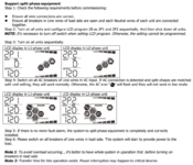
These inverters have changed internal config a few times, but as I understand it right now they are not N/G bonded. Someone else provided instructions below, but I have not bonded my panel.

1678655024496.png
 
Last edited:
To avoid these ads, REGISTER NOW!

mm08822

Well-known member
Joined
Jan 13, 2012
Messages
6,272
Location
NJ
While both inverters can each be outputting 120vac @60HZ without synching, the expected 240 vac may not be received at the EVC.
The EV charger may be detecting a phase shifted voltage if the 2 inverters are not synched for that type of output connection.
This is from the EG4 manual for split phase output configuration:
1678655365722.png

setup:https://signaturesolar.com/content/documents/EG4/6500ex/EG4_6.5_manual_revision2.pdf
Have you programmed the units for split phase?

This youtube video discusses some of the fault protection schemes for EVC's. You'll have to muddle through the 3 phase differences to that of a single phase unit and EU terms as they discuss the different protective schemes. Point being to understand the what the protection schemes are.
 

American Locomotive

Well-known member
Joined
Jan 8, 2017
Messages
11,153
Location
Rhode Island
It's important to remember that "ground" only works as a ground because at some point, somewhere, it's bonded to neutral. Many devices check the integrity of their ground connection by verifying a certain amount of resistance between the neutral and ground connections. If its outside of the expected range, it knows there is a problem.

When running on a generator (or a whole house inverter), at some point the ground connection of your home needs to make it back to the neutral bus of the inverter or generator - otherwise the ground will not work.
 

mm08822

Well-known member
Joined
Jan 13, 2012
Messages
6,272
Location
NJ
As long as the main panel neutral is bonded to ground at the main panel the connection is made and there should be zero potential between the 2 at any point in the system including a sub-panel unless that connection is interrupted. Interrupting the connection does not mean there is automatically a voltage potential difference unless a fault is occurring.

Post the details/manual of the EVC.

What is the voltage at the rv sub-panel: L1 - L2, L1 -N, L1-G, L2- N, L2-G? when on grid and then when on inverters?

Are the 2 inverters config'd for split phase?
 
OP
D

dcg9381

Well-known member
Joined
Jun 20, 2018
Messages
12,079
Location
Austin, TX
Have you programmed the units for split phase?

Yes. I've got split phase up and functioning just fine. Inverters communicate via serial port. I've put several 240V loads on the setup and it works great.

This has got to be related to the setup of a N/G bond. In particular, how should a bond be setup in the case where we are "mobile". IE, just like an RV. I assume you'd treat this case like an RV with an onboard generator. In such cases are the N/G bonded at the generator?

From [this video from Signature Solar|
(at 3:24) - it seems that I need to treat this like the RV case, install a ground bond on one inverter and depend on the relay in the inverter(s) to flip to grid power bond.

As long as the main panel neutral is bonded to ground at the main panel the connection is made and there should be zero potential between the 2 at any point in the system including a sub-panel unless that connection is interrupted. Interrupting the connection does not mean there is automatically a voltage potential difference unless a fault is occurring.

As setup right now, unless tied to grid, there is no N/G bond available in this system. I'm guessing (also) that this is my issue.

What is the voltage at the rv sub-panel: L1 - L2, L1 -N, L1-G, L2- N, L2-G? when on grid and then when on inverters?
I'll get that for you. Can you tell me what I'm looking for (typically) in a system that is not properly bonded N/G upstream of the panel?
can you provide make and model of EV charger?
Charge Point Home Flex - it detects a fault immediately. I can't get much from customer support other than that the fault code is "Code 25, Earth Fault detected". From what I read, all of them are going to be sensitive to improper grounding.
 
Last edited:

mm08822

Well-known member
Joined
Jan 13, 2012
Messages
6,272
Location
NJ
Yes. I've got split phase up and functioning just fine. Inverters communicate via serial port. I've put several 240V loads on the setup and it works great.

What type of loads? If they were just passive loads there wouldn't be any noticeable effects.
This has got to be related to the setup of a N/G bond. In particular, how should a bond be setup in the case where we are "mobile". IE, just like an RV. I assume you'd treat this case like an RV with an onboard generator. In such cases are the N/G bonded at the generator?
This EVC has a 20 mA trip.
1678726821553.png
1678726729636.png
CCID is a charge circuit interrupting device. New name for gfci protection. Either the system is detecting >20 mA imbalance
or
the voltages measured between each phase - grd is too different (this being beyond the scope of gfci protection) being an additional protective scheme within the EVC.

Since it is only a 2-wire 240volt input to the EVC, I'm tending toward the voltage difference being the cause.


From [this video from Signature Solar|
(at 3:24) - it seems that I need to treat this like the RV case, install a ground bond on one inverter and depend on the relay in the inverter(s) to flip to grid power bond.
But only having this connection at 1 inverter is a problem and a multiple inverters makes a different problem. You really need a 240v or 120/240 version as a single inverter.

Also as a test, if you have one, put a xformer in between inverter ac output and EVC input for isolation. This would balance the voltages relative to grd (and neutral) by bonding the center tap of the xformer secondary for either input source.
As setup right now, unless tied to grid, there is no N/G bond available in this system. I'm guessing (also) that this is my issue.
So force the n/g connection while on inverter. use a toggle switch between n/g to test.
I'll get that for you. Can you tell me what I'm looking for (typically) in a system that is not properly bonded N/G upstream of the panel?
As I stated in my original post, the voltages may be floating w/o proper reference to ground. Compare the differences seen by the EVC between the 2 inputs.
Charge Point Home Flex - it detects a fault immediately. I can't get much from customer support other than that the fault code is "Code 25, Earth Fault detected". From what I read, all of them are going to be sensitive to improper grounding.
Rather limited info. No manual to speak of.
 
OP
D

dcg9381

Well-known member
Joined
Jun 20, 2018
Messages
12,079
Location
Austin, TX
What type of loads? If they were just passive loads there wouldn't be any noticeable effects.

48A at 240V continuous loads. EVSE loads.


Let's assume I've got more than a 20mA "ground fault" - what's the right way to detect this with a meter (assume it does amps)

But only having this connection at 1 inverter is a problem and a multiple inverters makes a different problem. You really need a 240v or 120/240 version as a single inverter.

I'm not sure what you mean here. My panel is connected across both inverters in split phase. I don't have a single inverter that will do 240V and 12KW+ of power.


So force the n/g connection while on inverter. use a toggle switch between n/g to test.
What specifically do you mean here? Bond the panel as a test?


As I stated in my original post, the voltages may be floating w/o proper reference to ground. Compare the differences seen by the EVC between the 2 inputs.
My L1 to N and L1 to G measurements are the same 122V.


The "source" is not bonded - I'm still troubleshooting, but I think that's what I'm going to go after next. Reconfiguring the inverter with a bounding screw. Apparently there is a relay that switches that bond off when under grid power.
 

mm08822

Well-known member
Joined
Jan 13, 2012
Messages
6,272
Location
NJ
48A at 240V continuous loads. EVSE loads.
??? If you have run other loads that are EVCs then why mess with this other unit?

Let's assume I've got more than a 20mA "ground fault" - what's the right way to detect this with a meter (assume it does amps)
You will need a dvm that can read mA. Put it in series with the grd connection to the EVC.

I'm not sure what you mean here. My panel is connected across both inverters in split phase. I don't have a single inverter that will do 240V and 12KW+ of power.
I'm saying it's a mis-matched solution with this EVC. Do you have a xformer?

What specifically do you mean here? Bond the panel as a test? YES

My L1 to N and L1 to G measurements are the same 122V. And the rest of the readings? 10 total.

The "source" is not bonded - I'm still troubleshooting, but I think that's what I'm going to go after next. Reconfiguring the inverter with a bounding screw. Apparently there is a relay that switches that bond off when under grid power.
And multiple bond screws (1 in each inverter makes for a problem. (2 Inverters in parallel is the issue) Use the xformer approach.
 
OP
D

dcg9381

Well-known member
Joined
Jun 20, 2018
Messages
12,079
Location
Austin, TX
And multiple bond screws (1 in each inverter makes for a problem. (2 Inverters in parallel is the issue) Use the xformer approach.
Instructions from Signature Solar indicate that you only bond the "master" inverter. The inverters are tied together on the neutral and ground at the panel, so I assume one bond would actually bond both, but maybe that's wrong. Indications are that there is a relay / xformer that switches on/off when the inverter flips over to charge from the grid.

What I'm interested in is being able to detect this type of fault from a meter... Is it current between N/G that I'd be looking for? I understanding the reason for bonding at the source, but downstream separation on subpanels, I never bothered with the "why" and just did it like NEC says to do it.
 
To avoid these ads, REGISTER NOW!

American Locomotive

Well-known member
Joined
Jan 8, 2017
Messages
11,153
Location
Rhode Island
As setup right now, unless tied to grid, there is no N/G bond available in this system. I'm guessing (also) that this is my issue.
That is your issue.

The purpose of the ground wire in your devices is simply to provide an alternate path for electricity to flow through in the event of an issue. Typically ground wires are connected to the external housing or metal framework of something. So for example in an EV, if a hot wire were to somehow come in contact with the body of the vehicle, the current would be all shunted through the ground wire.

Current flows from hot to neutral - always. Ground wires only work because they're bonded to neutral. If while running under inverter power your ground wire is not bonded to neutral, any current on the ground wire would have no way to get back to the inverter.
 
OP
D

dcg9381

Well-known member
Joined
Jun 20, 2018
Messages
12,079
Location
Austin, TX
Thanks. So with an amp meter, should I look for current between L and G? Is that what's being detected in the EVSE?
 

American Locomotive

Well-known member
Joined
Jan 8, 2017
Messages
11,153
Location
Rhode Island
The EVSE will be doing a test to make sure there is a certain impedance between neutral and earth. If it doesn't detect any continuity, it knows there is a problem.
 

mm08822

Well-known member
Joined
Jan 13, 2012
Messages
6,272
Location
NJ
The EVSE will be doing a test to make sure there is a certain impedance between neutral and earth. If it doesn't detect any continuity, it knows there is a problem.
The EVC does not require a neutral. The only connections to it are 2 hots and an equipment grd. How can the EVC measure any impedance between neutral and grd when the neutral is not present at the charger?

Measuring voltages between each hot to grd, and hot-hot at the EVC is another story. It is probably expecting certain voltages (and tolerances) between the measurements, if the readings are out of spec, it faults.

I asked for several voltage readings when connected to grid source and then when connected to inverter output. These readings could easily explain how the fault is being triggered in the EVC and then the needed work around to eliminate the fault.
 

kaffine

Well-known member
Joined
Dec 13, 2009
Messages
3,610
Location
Henderson, NV
The EVC does not require a neutral. The only connections to it are 2 hots and an equipment grd. How can the EVC measure any impedance between neutral and grd when the neutral is not present at the charger?

Measuring voltages between each hot to grd, and hot-hot at the EVC is another story. It is probably expecting certain voltages (and tolerances) between the measurements, if the readings are out of spec, it faults.

I asked for several voltage readings when connected to grid source and then when connected to inverter output. These readings could easily explain how the fault is being triggered in the EVC and then the needed work around to eliminate the fault.

It can send a small current should be less than 5mA to avoid tripping GFCI down the ground. Does current flow? No then there is an issue with the neutral / ground bond. It could be an open ground wire going to the EVSE or a bad neutral ground bond. You need a neutral to fully test but you can determine there is a fault with only line and ground wire.

Sending a current down the ground can be used to verify there is a neutral ground bond. If it is missing then current wont flow. Note meter readings when there isn't a good ground / neutral bond can be misleading especially using digital meters as they require so little current flow they can have readings that aren't real due to capacitive and induced voltages.


To see what the EVSE is trying to do you can get a mA/uA clamp on meter. There are a few out there specifically marketed for testing GFCI issues. Clamp it around the ground wire and power up the EVSE and see what is anything is going through the ground wire. If testing a 120V outlet you could use a GFCI outlet tester and push the button and you should see a reading over 6mA on the ground when pushing the button, easier to see if the circuit isn't GFCI protected as it wont trip a breaker and stop.
 
OP
D

dcg9381

Well-known member
Joined
Jun 20, 2018
Messages
12,079
Location
Austin, TX
Thanks, guys. I've reflashed the inverters with "mobile" firmware and will get a G/N screw installed next time I can find a few hours in the shop. I'll report back after I make those changes.
 
OP
D

dcg9381

Well-known member
Joined
Jun 20, 2018
Messages
12,079
Location
Austin, TX
Appreciate the brain trust here.

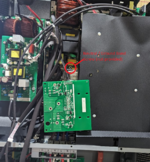
I patched this up tonight. I'm a little aggravated by having to open up brand new electronics and make changes a board. It's not surgery, but it's not exactly "consumer" level trivial either:

1679620208188.png

In addition to the screw, I had to update two bits of software firmware (per inverter).
As soon as I installed the required 2.5mm x 10mm screw, I got continuity between N / G outputs. I put it back together, fired it up, and I'm no longer getting faults on my EVSE. Inverters are pulling 77A each from the batteries, outputting about 7KW to the EVSE. The EV has about 97% charge, so I'll need to re-test after a few miles where the EVSE will demand more power.


1679620401190.png
 
OP
D

dcg9381

Well-known member
Joined
Jun 20, 2018
Messages
12,079
Location
Austin, TX
yup thats the ticket. for your project; your leave behinds will need bonding plugs for them as well.
Depends on the use case. When these inverters are in hybrid mode and charge from the grid, they make use of the panel bond apparently. My "understanding" is that that this bond gets passed through when inverting. It's only the "mobile" use case where the N/G isn't bonded.
 
To avoid these ads, REGISTER NOW!
Top Bottom