To avoid these ads, REGISTER NOW!

Fabricate metal ring for neon clock bezel?

miketyler

Well-known member
Joined
Sep 10, 2009
Messages
635
Location
Cedar Hill, TX
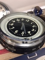
Hello all - I'm new to the F&T forums but not new to GJ or basic metal fabrication. I am looking for a way to fabricate a front bezel for an old Glo-Dial neon clock. Originals were stamped steel but in my research I have seen guys building similar shapes with bead rolling machines with custom dies.

The scope of this project may not be practical for the tooling I have access to but I'd be interested to talk about techniques as I try to find a shop that can do this. See the pic for an example. The ring I need to have built could be a simple round Z section, about 26"OD and could be made from steel or aluminum.

Appreciate any ideas on this you might have
 

Attachments

  • IMG_4572.JPG
    IMG_4572.JPG
    114.2 KB · Views: 79
  • IMG_4573.JPG
    IMG_4573.JPG
    120.3 KB · Views: 84
  • IMG_4574.JPG
    IMG_4574.JPG
    132.1 KB · Views: 77
To avoid these ads, REGISTER NOW!

Iron-Iceberg

Well-known member
Joined
Feb 14, 2006
Messages
887
Location
A-town
Not an easy part to make. There are a lot of those old clocks around does anyone re pop them? Will be the way to go.
 
OP
M

miketyler

Well-known member
Joined
Sep 10, 2009
Messages
635
Location
Cedar Hill, TX
The challenge would be capturing the the large standing leg of the Z and keeping it from deforming. Next way would be a welded assy I guess. Lot of finish work in that
 

NASTYZEN

Well-known member
Joined
Jun 11, 2010
Messages
2,823
Location
St-Colomban,Que. Canada
Not an easy part to fab up. A bead roller would probably be best. If there so rare. Make a few more to sell on the net to cover your costs. Or have some one else make them for you.
 
OP
M

miketyler

Well-known member
Joined
Sep 10, 2009
Messages
635
Location
Cedar Hill, TX
Yes, I plan to. There's lots of these old neon clocks out there that have been derelict from their front bezels. I can't find anyone that does this type of work in the DFW area so far
 

txvwnut

Well-known member
Joined
Jan 1, 2015
Messages
7,626
Location
Bedford, Texas
How heavy of a gauge steel are you planning on using, a shrinker stretcher combo might get you what your after.
 

b-dog

Well-known member
Joined
Apr 24, 2015
Messages
239
Location
Lakewood, CO
I think the easiest and probably most costly option would be machining. You could get that machined easily if you had a drawing. I could have the part quoted and machined in a couple weeks, bam DONE. Machining would be pricey but you wouldn't have to deal with the art of rolling/curving which IS an art. Personally, I'm not artsy so I know I would get frustrated and give up before I created anything that I liked.

The challenge would be capturing the the large standing leg of the Z and keeping it from deforming. Next way would be a welded assy I guess. Lot of finish work in that

That's just a matter of stretching the correct area. I'm in the metal roofing industry and people curve 2" tall legs with extra bends at the top on both sides of a panel.

0dbc3dd1-aaff-4607-96b5-79ed2586419b.jpg


curved-roof-001-large.gif


The curving machines that make those panels just squeeze the legs in order to stretch them. You might have to run the panel through the machine a few times to get the radius that you need.
 
OP
M

miketyler

Well-known member
Joined
Sep 10, 2009
Messages
635
Location
Cedar Hill, TX
Agreed. Machining from solid stock would be crazy expensive with a lots of waste. I haven't ruled out welded assy but even that would take some skills to keep it from warping with the thin gage metal needed. That is some interesting roof sections there.
 
To avoid these ads, REGISTER NOW!

EdT

Well-known member
Joined
Sep 21, 2010
Messages
1,104
Location
North Georgia
Can you post a sketch of the cross section with a few dimensions, angles etc and how thickis the material required?
 

INSP380

Well-known member
Joined
Dec 17, 2012
Messages
909
Location
Cleveland, Ohio
Call Chicago Metal Rolled Products. We buy flatbar rolled the hard way and rolled angle from them. They can make it.

Steve
 
Last edited:
OP
M

miketyler

Well-known member
Joined
Sep 10, 2009
Messages
635
Location
Cedar Hill, TX
Thanks for the comments. Good call on the bike wheel only I'd have to cut one of the legs and weld on to the opposite side to form the Z. Still might be better than welding both legs!

I could get by with standard Z-section, 3/4" horizontal legs and 2" standing leg. Both horizontal flanges would be at 90* to the standing leg.

I could form up such a Z-section from .032 or .040 aluminum and possibly shrink or stretch it. There would be a lot of clean up and some material loss but might be doable shrinking the inside leg and stretching the outside. Maybe build it in two halves and TIG weld them together? Thanks, INSP380. Will check with CMRP.

Appreciate the responses, this is the type outside-the-box feedback I am looking for.
 

Whiskeymike

Well-known member
Joined
Oct 31, 2013
Messages
775
Location
Austin, TX
Are you trying to reproduce it exactly or is a similar ring acceptable?

If I was going to do it, I would cut a 20-22 gauge recatangle longer than the circumference requires. Then I would put the two bends in it with a brake at the width you need.

Then I would use a shrinker and stretcher to round the piece. Stretcher on outside edge, shinker on inside. It'll automatically turn into the round circle. Keep going till it's the diameter you need. It should be overlapping the ends. Cut one side to be 1/16Th short. Weld, planish and grind the welds flat. Then if needed use bead roller for contour on edges to round them.

Probably a lot of trial and error in between.

The other thing that would be worth trying...

If you have access to a shop bot cnc router, you might make a male/female die from mdf and then press it in a press. That's probably how it's made except in a steel die. Again, it's going to be really tough to get it exact.
 
OP
M

miketyler

Well-known member
Joined
Sep 10, 2009
Messages
635
Location
Cedar Hill, TX
Hi Mike - yes, that was my original plan was to work with a straight Z section. I'm more familiar with aluminum and could easily see it cracking from stretching on the outer flange. Should be weldable though. I'd be happy with a simple Z or slightly offset Z. I can hand-roll the outer edge with a 1/8" break so it rolls over the edge of the can nicely.

I dont have access to any nice equipment; will MDF hold up for thin metal stamping as this?
 
OP
M

miketyler

Well-known member
Joined
Sep 10, 2009
Messages
635
Location
Cedar Hill, TX
That's a cool little device for working thin soft metals. My edge roller we used on aircraft skins did the trick for making a clean 1/8" break on the edge to make it "tuck in" to the wing spars.

Thinking thru the single section approach puts me at about a 7ft long piece. My finger brake is only 4ft long. I may need to check in with my old pals back at the airport and see if I can call in a favor.
 
Last edited:

EdT

Well-known member
Joined
Sep 21, 2010
Messages
1,104
Location
North Georgia
So, it sounds like you're wanting to make the rear bezel part that is black in your original photos. Is that correct?
 
OP
M

miketyler

Well-known member
Joined
Sep 10, 2009
Messages
635
Location
Cedar Hill, TX
No, its the chrome piece in the pics. That example is another Glo-Dial that's 22" in dia. I am not trying to replicate it perfectly. Just looking for a functional part for now. This is the clock its being built for:
 

Attachments

  • Glo_dial.jpg
    Glo_dial.jpg
    138.7 KB · Views: 26
  • IMG_4082.JPG
    IMG_4082.JPG
    123.4 KB · Views: 11
  • IMG_4083.JPG
    IMG_4083.JPG
    91 KB · Views: 11
To avoid these ads, REGISTER NOW!
Top Bottom