To avoid these ads, REGISTER NOW!

Fabricated Drill press? Kit, maybe?

ntsqd

Well-known member
Joined
Jan 22, 2005
Messages
965
Location
Lower left coast
I ran a search, but that doesn't mean that I didn't miss it.

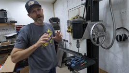
SnoCats and similar vehicles fascinate me for some inexplicable reason so I've been following MORR's "Bombi" series of videos (with the mute and CC on and the play-back set at 2X) when this one caught my eye. Have a look at it at about 3:08-3:10


What I see in the background is a drill press with an impressive throat height, rigid column, direct drive motor with likely a VSD, Albrecht (or clone) keyless chuck, and a potentially flimsy looking table (I do see a diagonal support under it) that doesn't look all that easy to adjust for height. I have some thoughts on that, but figured I'd first see if this is a kit that I've not found yet or if it is something that the guy, Tom, likely built from scratch.
 
To avoid these ads, REGISTER NOW!

seber

Well-known member
Joined
May 31, 2016
Messages
4,195
Location
Deep East Tx.
That's a 36 minute video that most people are not going to be interested in. How about telling us where to look in the video.
 

Under_Pressure

Well-known member
Joined
May 13, 2014
Messages
113
Location
NE Wisconsin
That's a 36 minute video that most people are not going to be interested in. How about telling us where to look in the video.
He said "Have a look at it at about 3:08-3:10." Which I did, and it's super cool. Guessing it's custom. With that much travel on the spindle, you probably could get away with having no adjustment on the table, or at least with it it being a little more difficult than you would normally want (i.e. bolted to the column or something). My biggest question is how the spindle itself is set up- it looks like a drill chuck simply attached to the end of a motor, but obviously there has to be something more to it as a standard electric motor shaft/bearings can't support those kinds of loads. Plus there would need to be a way to attach tooling (chuck, etc.), typically a morse taper. Maybe that's some kind of special motor/spindle combo taken from an old machine tool?
 
OP
N

ntsqd

Well-known member
Joined
Jan 22, 2005
Messages
965
Location
Lower left coast
Chuck attachment can be figured out, I don't think that it would be too difficult. Whether or not the bearings in a face mount motor can take the spindle loads is a whole different concern. I'm not inclined to think so, which means it needs a thrust bearing of some sort.
Might be able to use one of these Hougen accessories as the jumping-off point to create the spindle: https://hougen.com/accessories/accessories_index.html#arbor

Were I going to build it, and I'm considering it even though I have a 30's era production drill press, I would use a Weldon type interface as the primary connection so that Hougen type annular cutters could attach directly to the spindle in place of the drill chuck.

Thanks for the screen grab! I'm still trying to work out exactly how the motor assembly is both moved up and down and doesn't fall when left alone.
 

seber

Well-known member
Joined
May 31, 2016
Messages
4,195
Location
Deep East Tx.
Chuck attachment can be figured out, I don't think that it would be too difficult. Whether or not the bearings in a face mount motor can take the spindle loads is a whole different concern. I'm not inclined to think so, which means it needs a thrust bearing of some sort.
Might be able to use one of these Hougen accessories as the jumping-off point to create the spindle: https://hougen.com/accessories/accessories_index.html#arbor

Were I going to build it, and I'm considering it even though I have a 30's era production drill press, I would use a Weldon type interface as the primary connection so that Hougen type annular cutters could attach directly to the spindle in place of the drill chuck.

Thanks for the screen grab! I'm still trying to work out exactly how the motor assembly is both moved up and down and doesn't fall when left alone.
There are what looks like a pair of chains attached to the top of the motor carriage. I'm guessing those are attched to a counterweight.
 
OP
N

ntsqd

Well-known member
Joined
Jan 22, 2005
Messages
965
Location
Lower left coast
That is one guess that I've had from the beginning.
At 4:08 there is more footage of the tool that clearly shows the chains wrapped over a pair of idler sprockets at the top of the column, so counterweight seems most likely.
At 4:17 the brand name on the keyless chuck is visible, but not quite legible to my eyes. Guessing that it might be this chuck: https://www.mscdirect.com/product/details/15892284
 
OP
N

ntsqd

Well-known member
Joined
Jan 22, 2005
Messages
965
Location
Lower left coast
If you happen to know where it is I'd be grateful as I can't find it. I knew nothing of it until just a couple days ago.
 

dyermullet

Well-known member
Joined
Sep 9, 2017
Messages
60
Location
TX
Google found discussion about the drill press:


I would assume this is the typical YouTube sponsor product placement.


To avoid these ads, REGISTER NOW!

Firebrick43

Well-known member
Joined
May 12, 2015
Messages
14,024
Location
West central Indiana
While the general idea isn’t far off from a bed mill head, the implementation is garbage.

From using the motor bearings to take all the forces to using Vee rollers for the head carriage but instead of running them on vee ways running the on a piece of channel welded to the column. Didn’t even knock the mill scale off.

No way in hell will that carriage run straight and free while having little free play. It will be the opposite because of how unceremoniously it was cobbled together
 
OP
N

ntsqd

Well-known member
Joined
Jan 22, 2005
Messages
965
Location
Lower left coast
From experience I would say that we don't know enough, and can't see enough about the execution of the design from the limited pictures available to adequately critique it. It is possible that all of your points, except the mill scale, have been addressed and are not visible or obvious from the pictures. Or not.
 

Firebrick43

Well-known member
Joined
May 12, 2015
Messages
14,024
Location
West central Indiana
They are visible
From experience I would say that we don't know enough, and can't see enough about the execution of the design from the limited pictures available to adequately critique it. It is possible that all of your points, except the mill scale, have been addressed and are not visible or obvious from the pictures. Or not.
I respectfully disagree. The pictures are very clear on what is lacking

The A36 channel is welded on as rolled. It is neither machined on the top edge(red arrow) with a 90 degree angle to match the Vee roller(blue arrow) but left as is. That is very obvious no care was given to a proper carriage for the head. Ideally instead of machining a 90 degree Vee the edge(red) and face(green) would be machined square and 90 to each other and parralle to the opposite side of the channels and to the back of the column. Then a premanufactured and hardened Vee way would be bolted to the trued up surfaces. They are fairly cheap and available from even McMaster Carr and would give better wear than the soft A36 channel being machined and having rollers directly on it.

fdp6yk4l.png

The correct profile for the Blue rollers to ride.
dualvee_track_square.png

The motor is clearly an off the shelf 3 phase TEFC C face motor, a dayton one at that. :puke:

These motors have deep groove ball bearings. As the motor has to be under 1 hp for use on a 120V circuit

Easy to narrow it down to a dayton 48ZK02 motor,

Dayton Data sheet.

The deep groove ball bearings are not designed to handle much thrust load as this drill press applies but from radial loads like belts.

You can tell that thrust bearings have not been installed.

There is obviously no supporting thrust bearings installed in the blue plate. And one can not retrofit thrust or angular contacts into the OEM diecast motor housing end casting(red) There is no room to do so and the light casting has minimal axial strength. It would be possible to machine a custom end housing but its obvious that they have not done so.
cih8lfig.png
 

slowtwitch73

Well-known member
Joined
Apr 18, 2019
Messages
5,876
Location
Hellgate
Compared to the dp those guys were using, anything is an upgrade.

They lean towards the hackish end of things anyways.. sure they are happy with it... esp for free.
 
OP
N

ntsqd

Well-known member
Joined
Jan 22, 2005
Messages
965
Location
Lower left coast
They are visible

I respectfully disagree. The pictures are very clear on what is lacking

The A36 channel is welded on as rolled. It is neither machined on the top edge(red arrow) with a 90 degree angle to match the Vee roller(blue arrow) but left as is. That is very obvious no care was given to a proper carriage for the head. Ideally instead of machining a 90 degree Vee the edge(red) and face(green) would be machined square and 90 to each other and parralle to the opposite side of the channels and to the back of the column. Then a premanufactured and hardened Vee way would be bolted to the trued up surfaces. They are fairly cheap and available from even McMaster Carr and would give better wear than the soft A36 channel being machined and having rollers directly on it.

fdp6yk4l.png

The correct profile for the Blue rollers to ride.
dualvee_track_square.png

The motor is clearly an off the shelf 3 phase TEFC C face motor, a dayton one at that. :puke:

These motors have deep groove ball bearings. As the motor has to be under 1 hp for use on a 120V circuit

Easy to narrow it down to a dayton 48ZK02 motor,

Dayton Data sheet.

The deep groove ball bearings are not designed to handle much thrust load as this drill press applies but from radial loads like belts.

You can tell that thrust bearings have not been installed.

There is obviously no supporting thrust bearings installed in the blue plate. And one can not retrofit thrust or angular contacts into the OEM diecast motor housing end casting(red) There is no room to do so and the light casting has minimal axial strength. It would be possible to machine a custom end housing but its obvious that they have not done so.
cih8lfig.png
While I don't agree with all of your assumptions and conclusions I'm going to agree to disagree and stop there.

As to the price, it is too much for what is there and how it's made. They're also working against any Economies of Scale that will benefit higher volume mfg's of machine tools. From the looks of it they are building them in lots of 10. No way they're getting any kind of volume price break on the parts and components at a prototype level production volume. I suspect that it would take lots of 1000 for volume price breaks to make much difference in cost, and I just don't see that happening.
 

Firebrick43

Well-known member
Joined
May 12, 2015
Messages
14,024
Location
West central Indiana
While I don't agree with all of your assumptions and conclusions I'm going to agree to disagree and stop there.

As to the price, it is too much for what is there and how it's made. They're also working against any Economies of Scale that will benefit higher volume mfg's of machine tools. From the looks of it they are building them in lots of 10. No way they're getting any kind of volume price break on the parts and components at a prototype level production volume. I suspect that it would take lots of 1000 for volume price breaks to make much difference in cost, and I just don't see that happening.
There is no assumptions, its all clearly visible in the pictures, in contrast to your assertion if post 14.

I find it odd that you are activly trying to defend a tool but wont provide any substantive debate at all on a tool forum?

Not only the methods of construction but now the price as well?
 
OP
N

ntsqd

Well-known member
Joined
Jan 22, 2005
Messages
965
Location
Lower left coast
There is no assumptions, its all clearly visible in the pictures, in contrast to your assertion if post 14.

I find it odd that you are activly trying to defend a tool but wont provide any substantive debate at all on a tool forum?

Not only the methods of construction but now the price as well?
You claim the motor is 120VAC, yet they only offer an adapter for that, normally it runs on 208-240 per the post above and their page.

A Dayton motor isn't the end of the World. In some circumstances they are the best motor for the job. I'm talking the whole picture, not just the myopic most ideal motor period. I don't normally buy them either, but in a tightly constrained budget I will and have.

You have no way of knowing if the "rail" that the V rollers ride on has been inducted hardened, yet you claim it to be soft. I can't claim that it is and I've made no such assumptions, but I am acknowledging that it is a possibility.

You make assumptions about the tracking of the carriage, yet the edge of that "rail", at least in one pic (yours) has clearly been machined on the edge. No that won't make it track like it is a mill, but that's OK because it is a drill press. It shouldn't be expected to track and repeat like a mill.

Yes, it would be better served to ride on a V shaped rail. The ROI isn't there for a drill press. The edge of a flange is an economic solution to that challenge. I doubt that you can find an average drill press like most of us use that is any more rigid or repeatable in it's tracking.

I work in tooling design, I have some idea of what these things cost. My assumptions about the Economies of producing this tool are based on that ~45 years of experience. No, I wouldn't buy one at that price. I'd build one and it likely would cost me more because I'd upgrade some of the design features.

Your tone isn't debate, it's attack. Since I am the person who brought this whole thing up it appears to be an attack on me. I'm not defending the tool or it's maker, I'm defending what feels like an attack on me.

Right now if there were a delete option this thread would be gone. As it is, I am done from this thread.
 

uart

Well-known member
Joined
Nov 17, 2011
Messages
1,226
Location
Australia
Well in to serious industrial spec drills at that price. Really nice gear head drills or a small radial arm drill.
Also worth considering that there could be torque limitations at low speed on a direct drive unit like that (in comparison with something that gears down the motor to achieve low speed operation).

A good VFD can give full load torque at low speed, but that still results in power that falls in direct proportion to speed. This isn't the case with geared or pulley speed reduction.
 

Firebrick43

Well-known member
Joined
May 12, 2015
Messages
14,024
Location
West central Indiana
You claim the motor is 120VAC, yet they only offer an adapter for that, normally it runs on 208-240 per the post above and their page.
No, I didn’t claim the motor was 120v. I very clearly posted a link (Post 16) that showed that the motor was 208-240v. I said it has to be under 1hp for it to be used on 120v circuit.

The VFD can take either 120v or 240v input single phase and convert it to 240v 3 phase. The adapter is strictly for the cord end. A vfd that can have a 120v input is limited to 1 hp motor or less output because of amps.

A Dayton motor isn't the end of the World. In some circumstances they are the best motor for the job. I'm talking the whole picture, not just the myopic most ideal motor period. I don't normally buy them either, but in a tightly constrained budget I will and have.
It doesn’t matter if it’s a Dayton or a better Leeson, Baldor, Weg. A standard off the shelf 3phase 56c motor of any manufacture does not have the bearing to properly deal with the thrust load nor the space to add the needed bearing into their die cast end housings.
A 6204 deep groove bearing is not designed for major thrust loads.

You have no way of knowing if the "rail" that the V rollers ride on has been inducted hardened, yet you claim it to be soft. I can't claim that it is and I've made no such assumptions, but I am acknowledging that it is a possibility.
I know because structural steel channel is A36 low carbon steel. As a condition of being made of low carbon steel It can not be induction hardened. The only way to harden A36 steel is to case harden it. And it could not been case hardened because the mill scale is still on the piece.
Yes, it would be better served to ride on a V shaped rail. The ROI isn't there for a drill press. The edge of a flange is an economic solution to that challenge. I doubt that you can find an average drill press like most of us use that is any more rigid or repeatable in it's tracking.
Nearly every drill press can. Structural steel has terrible tolerances. If it would of been machined after welding I would have formed a different opinion.
I work in tooling design, I have some idea of what these things cost. My assumptions about the Economies of producing this tool are based on that ~45 years of experience. No, I wouldn't buy one at that price. I'd build one and it likely would cost me more because I'd upgrade some of the design features

Your tone isn't debate, it's attack. Since I am the person who brought this whole thing up it appears to be an attack on me. I'm not defending the tool or it's maker, I'm defending what feels like an attack on me.

Right now if there were a delete option this thread would be gone. As it is, I am done from this thread.
I am baffled on how you think I am attacking you.
I have done nothing but point out flaws in the design of the machine. Unless you are the designer how is that an attack?

I did challenge your personal attacks when in post 14 when you stated that I was blind and "couldn't see enough" even though the pictures are perfectly clear.
And in post 19 that I was just making "Assumptions" without any discussion as why.

And it shouldn't be deleted as people should be warned about that drill press
 
Last edited:
To avoid these ads, REGISTER NOW!
Top Bottom