To avoid these ads, REGISTER NOW!

Fabricating a HD Engine Stand

Mad4wd

Member
Joined
Mar 11, 2008
Messages
22
Location
Youngstown, Ohio
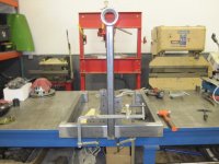
I have been a long time "lurker" so I figured I would start sharing some of the projects and stuff we do here at my shop. We are building a heavy duty engine stand and I thought I would post some pics, as I so enjoy reading all the threads of the stuff you guys have going on. I hope you enjoy.

Larry

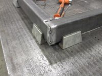
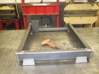
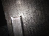
The material is 2" x 4" by 3/16" A36 Structural. We used about 12' to do this. If anyone wants specific measurements, just send me a pm or post.
 

Attachments

  • misc 162.jpg
    misc 162.jpg
    121.8 KB · Views: 108
  • misc 161.jpg
    misc 161.jpg
    122.7 KB · Views: 105
To avoid these ads, REGISTER NOW!
OP
M

Mad4wd

Member
Joined
Mar 11, 2008
Messages
22
Location
Youngstown, Ohio
We use corner clamps. We notched the tubing so we would also not have to build caps later for it. The makeshift spreader bar at the end was used to just stop the legs from pulling in as we welded them.
 

Attachments

  • misc 163.jpg
    misc 163.jpg
    141.8 KB · Views: 104
  • misc 164.jpg
    misc 164.jpg
    125.2 KB · Views: 113
  • misc 165.jpg
    misc 165.jpg
    106.2 KB · Views: 105
OP
M

Mad4wd

Member
Joined
Mar 11, 2008
Messages
22
Location
Youngstown, Ohio
After its all welded, this is what you should have. Then you could knock out the spreader. You then need to decide how tall you want it. Make sure you take into account what casters you plan on using and their height.
 

Attachments

  • misc 171.jpg
    misc 171.jpg
    106.6 KB · Views: 124
  • misc 167.jpg
    misc 167.jpg
    115.7 KB · Views: 99
OP
M

Mad4wd

Member
Joined
Mar 11, 2008
Messages
22
Location
Youngstown, Ohio
This is how we did the upright. We notched the tubing to slip over the lower frame. We also fit the upper bearing holder to the upright and ground for clearance to get a good fit up to weld.
 

Attachments

  • misc 174.jpg
    misc 174.jpg
    110.6 KB · Views: 107
  • misc 172.jpg
    misc 172.jpg
    122.5 KB · Views: 91
  • misc 185.jpg
    misc 185.jpg
    124.8 KB · Views: 84
OP
M

Mad4wd

Member
Joined
Mar 11, 2008
Messages
22
Location
Youngstown, Ohio
We had to extend the width of the edge of the stand to support the casters. Are casters mounting bases are 4" by 4.5". We are using two smart and two dumb casters that are pretty heavy duty for this...we don't want any failures. We then built caps and welded them onto the stand.
 

Attachments

  • misc 182.jpg
    misc 182.jpg
    129 KB · Views: 100
  • misc 180.jpg
    misc 180.jpg
    122.9 KB · Views: 76
  • misc 179.jpg
    misc 179.jpg
    116.5 KB · Views: 71
  • misc 177.jpg
    misc 177.jpg
    105.5 KB · Views: 62
  • misc 176.jpg
    misc 176.jpg
    113.4 KB · Views: 60
  • misc 175.jpg
    misc 175.jpg
    119.6 KB · Views: 60
  • Casters.jpg
    Casters.jpg
    142.3 KB · Views: 58
OP
M

Mad4wd

Member
Joined
Mar 11, 2008
Messages
22
Location
Youngstown, Ohio
We ground and buffed all the edges so it looks good and there is nothing hanging around to cut you later. We then began to layout the parts we used for the head. The head will rotate and be on tow bearings with a 4wd lockout at the opposite end. This enables you to rotate and lock the engine at any angle you want and basically spin it with one hand.
 

Attachments

  • misc 183.jpg
    misc 183.jpg
    54.9 KB · Views: 167
  • misc 184.jpg
    misc 184.jpg
    135.6 KB · Views: 160
Last edited:
OP
M

Mad4wd

Member
Joined
Mar 11, 2008
Messages
22
Location
Youngstown, Ohio
We now needed to position and fixture the head correctly. After we built a makeshift holding fixture to ensure it was square, we welded our machined steel sleeve to our upright.
 

Attachments

  • misc 188.jpg
    misc 188.jpg
    115.8 KB · Views: 116
  • misc 187.jpg
    misc 187.jpg
    91.1 KB · Views: 113
  • misc 186.jpg
    misc 186.jpg
    66.6 KB · Views: 87
OP
M

Mad4wd

Member
Joined
Mar 11, 2008
Messages
22
Location
Youngstown, Ohio
Now that the head was welded, we needed to place the upright into place. We have a bunch of steel blocks we use for jigs and fixtures on the weld tables and cnc machines, so we grabbed some of them and clamped them in place to make sure we stayed square to the lower frame. We then finished welding it into place.
 

Attachments

  • misc 189.jpg
    misc 189.jpg
    101 KB · Views: 131
  • misc 190.jpg
    misc 190.jpg
    92.8 KB · Views: 119
  • misc 192.jpg
    misc 192.jpg
    105.9 KB · Views: 156
OP
M

Mad4wd

Member
Joined
Mar 11, 2008
Messages
22
Location
Youngstown, Ohio
I need a few more days to machine the head plate, arms and rest of the parts. I will add the pics and updates as we go. I did forget to add that we cut 1/8" plates to go on the bottom of the stand to serve as mounting plates for the casters on all four corners.

Larry
 
To avoid these ads, REGISTER NOW!

35mastr

Well-known member
Joined
Dec 6, 2007
Messages
2,534
Location
Norcal
I am also interested in all the head parts if you want to sell them as a kit.
Very nice work.
 

472scout

Well-known member
Joined
Sep 18, 2010
Messages
1,276
Location
back 40
We ground and buffed all the edges so it looks good and there is nothing hanging around to cut you later. We then began to layout the parts we used for the head. The head will rotate and be on tow bearings with a 4wd lockout at the opposite end. This enables you to rotate and lock the engine at any angle you want and basically spin it with one hand.

I can see spinning it with one hand if the engine is balanced on the fixture. Usually an engine with heads is very top heavy though. Are you just going to use the typical tube handle or do you have something more interesting in mind? Some of the more expensive engine stands have a ratcheting system.
 

Mr.N

Well-known member
Joined
Jul 13, 2005
Messages
2,221
Location
Mpls, MN
We ground and buffed all the edges so it looks good and there is nothing hanging around to cut you later. We then began to layout the parts we used for the head. The head will rotate and be on tow bearings with a 4wd lockout at the opposite end. This enables you to rotate and lock the engine at any angle you want and basically spin it with one hand.
Very nice, I don't see the lockout or axle shaft in any of the pics.

How are you going to secure the axle shaft from turning?
 
OP
M

Mad4wd

Member
Joined
Mar 11, 2008
Messages
22
Location
Youngstown, Ohio
Guys, Since I have had more than a few requests for the parts for these, let me see what it is going to cost to get a kit together. What would you like to see in it? I was thinking the machined steel head, the spindle, a section of splined shaft, lockout and the bearings and seal? We could also do the rear face plate and arms as a separate part or include it also. I do not want anyone to have sticker shock on the parts though as the lockout alone is 75.00.

Larry
 
OP
M

Mad4wd

Member
Joined
Mar 11, 2008
Messages
22
Location
Youngstown, Ohio
I can see spinning it with one hand if the engine is balanced on the fixture. Usually an engine with heads is very top heavy though. Are you just going to use the typical tube handle or do you have something more interesting in mind? Some of the more expensive engine stands have a ratcheting system.

Scout:
We have already built one of these a few years ago and we used a machined tube handle. What we did is when we built the face plate and arms, we made them so the engine center line could be lowered thus getting close to a balance point. The worse ones of course are 6-cyl's. We noticed as long as you had two hands on it and a guy running the lockout, you were pretty safe. The issue is there is no drag per say in the head, if it wants to come around, she is coming around and that is that..lol
Larry
 
OP
M

Mad4wd

Member
Joined
Mar 11, 2008
Messages
22
Location
Youngstown, Ohio
Very nice, I don't see the lockout or axle shaft in any of the pics.

How are you going to secure the axle shaft from turning?

Mr.N,
Here is a picture of the shafting and the lockout on the one we built a few years ago. The spindle and the shaft will both be welded to the face plate after the slots are machined and it is bored for machined spindle and shaft material.

Larry
 

Attachments

  • CNC 001.jpg
    CNC 001.jpg
    84.6 KB · Views: 121
  • CNC 002.jpg
    CNC 002.jpg
    123.8 KB · Views: 93
OP
M

Mad4wd

Member
Joined
Mar 11, 2008
Messages
22
Location
Youngstown, Ohio
That is possible if you can find a yard willing to let you pilf 35-spline lockouts off of perfectly good axles that are worth between 500 and 1K dollars. The 30-spline ones are everywhere...35-spline not so much in our experience. That is no problem though by all means you can do that...we just build things to a certain level and we do not use too many recycled parts, but to each their own.

Lar
 
To avoid these ads, REGISTER NOW!
Top Bottom