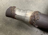
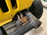
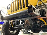
Here’s the old steering box. After a little education, I learned that this is a Mercedes box which they put only in the 2003 - 2006 Wranglers. I think the Daimler/Chrysler merge happened around this time but I have no idea why they decided to change out a known working thing. The previous box was a saginaw which was used in just about every 4 wheel drive I’ve worked on dating back to the 70’s. Regardless, bad idea, it’s going away.

Here’s a walk trough of the stretch kit and how it works. This is a shot of the drivers side stock frame rail. The factory (crappy) steering box attaches with 3 bolts. One goes through the frame and the other two go through that scabbed on box-looking thingy.

A pair of side-plates with holes to locate the new thru-frame sleeves are welded on sandwiching the frame rail.

The side-plates also locate the new cross-member tube which is smaller and shifts as far as possible forward to help make room for the box to rotate up.

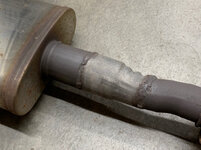
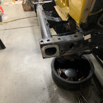
Here’s the difference between the old and new cross-member tubes. The factory tube has a D-shaped end which requires custom sleeves for aftermarket sway bars. This new DOM tube is smaller, stronger, takes up much less space, and uses a much easier to machine bushing for the sway bar.

The bulky body mount comes out with the cross-member and a newer more trim version is welded in to replace it. The kit came with two different versions so I have to choose: (1) I can delete the 1” body mount at the grill and used the raised mount or (2) I can install the stock mount and retain the body lift bushing. I wait to make this decision until the very last. I may need the room the body mount offers.

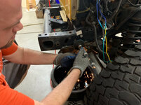
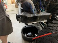
Start by removing the power steering lines to the box.

Catch as much of the fluid as possible

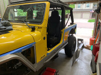
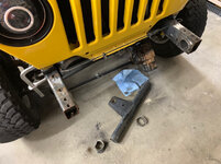
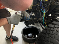
Pull the steering box bolts so that I can rotate it out of the way. I’ll leave it hooked up for now so I don’t need to worry about the steering wheel losing center (though I’m not sure it matters).

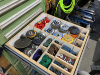
I try to keep on hand a variety of discs (grinding, cut-off, and flapper) in a variety of sizes for the various tools necessary to metal work. This drawer had become somewhat bare in recent years given how little metal fabrication I’d been doing. In prep for this project I’d recently replenished so there’d be nothing left to want in the moment (and more importantly cause me to have to go the store).

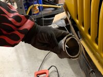
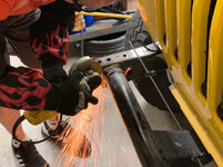
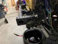
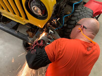
Now to remove the steering box bracket/box thing hanging off the bottom of the frame. I start by slicing down into the welds on either side until I’m mostly through the weld. I keep the cuts shallow as to not cut into the frame itself.

An air hammer with a weld shear bit splits/fractures whats left of the welds and the bracket nearly falls off in my hands leaving only traces of the welds that once held it on.

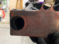
The manufacturer uses thru-sleeves to give a solid but light weight mounting point. Remember this for later as this them reoccurs in a few if the aftermarket parts I’ll be installing.

Mini-flapper disk on a right angle grinder makes quick work of what was left behind. Historically I used flapper discs on a 4 1/2-inch angle grinder for tasks like this but ever since finding these 3” flapper discs the angle grinder is my go to for basic clean up.

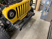
Now I need to clean up the remaining nonsense protruding from the outside of both frame rails so I can take some reference measurements for width and angle.

I do that by first trimming off as much as I can with my sawzall. Though it seems like a barbaric tool, it can be used for precision work with a little practice. The remaining protrusion is then ground down and sanded smooth.

With both sides flat, I can now take reference measurements. I start by getting the frame level. A little trick here - a frame is neither square nor level. The manufacture does all kinds of **** to make a car look like it’s sitting level but precision the frame is not. If the vehicle sits level (and this one did) then all you need to do is make it the same as it was. To help, I jack up the frame until the cross-member is zero’d out and level.

Then take measurements on either side of the frame noting 3 different spots. With these measurements I’ll know if the rails are splaying out, in, etc and will have an opportunity to compensate before everything gets welded together.

Next to deal with the cross-member but first I need to make sure that the weight of the engine doesn’t splay out the frame rails after it’s removed. To prevent that, I’ll heavy tack-weld an angle iron across the rails below the radiator.

With this temporary brace in place, surgery can start.

The fastest and cleanest way to remove the crossmember is with a sawzall but the flexible blade can make precision work difficult if you’re starting on a weld. To create a starting groove, I use a cutoff wheel on the 4 1/2” grinder and grind a groove maybe 1/8” inside the frame rails for bandsaw blade to track in.

Then, I make a wild cut a few inches in to remove the bulk of the crossmember. With this out of the way I’ll have visibility inside the tube as I cut next to the frame rails. This will allow me to get as close as possible without actually cutting into the rail itself.

Now it’s time to be precise. The blade is just barely long enough to make it all the way through on the retraction stroke.

It took me a bit to trim them off. I had to cut through the tube and upper and lower half moon gussets. Sawzall manages just fine and the blade is still good for another job down the road.

Ready for the stretch kit.