To avoid these ads, REGISTER NOW!

filter size formula

SGKent

Banned
Joined
Feb 12, 2010
Messages
1,959
Location
Citrus Heights CA
Without going online to research it, which I have already done, does anyone have a formula for determining optimal filter size for a given CFM using the higher MERV filters? Example - a 1000 CFM air handler requires X filter area when a higher MERV filter is used. A 1250 CFM air handler requires Y filter area when a higher MERV filter is used.

I don't have the ability, time and money to build a series of returns and stick different filters on them to see when the pressure falls to acceptable levels. In this case acceptable would be .15" wc or less. I'd like to get below .10" wc if possible.

The split system runs between 1000 to 1200 CFM depending on where I set the motor, and currently has two filters for a total of 678 sq inches or 4.7 sq ft. That works perfect with a MERV 1 fiberglass filter however when a pleated high MERV filter with the lowest resistance available is used, the pressure drop rises above the design limit. I need a formula for calculating optimal filter area when a higher MERV filter is used. The local HVAC folks can only guess.

So far the best formula I can find online is to use is, "Filter Area = 2.0 square feet (or more) for each 400 cfm of air flow." So 1000 \ 400 = 2.5 tons X 2.0 = 5.0 sq ft minimum at 1000 CFM or 1200 \ 400 = 3 tons x 2.0 = 6.0 sq ft minimum. I don't want to have a new return built, cut the wall to install it and find out that formula falls short. On the other hand I don't want to guess large and make a whole wall a return grille either. Someone else in the same article the 2.0 X ton number came from uses 3.0 X ton, which changes the numbers to 7.5 sq ft and 9 sq ft. Somewhere out there is a formula that can be relied on.

Also - does anyone know - if you have a filter that is say .28" wc at 1040 CFM and you parallel it with an identical filter, does the pressure drop to .14" wc because the surface area is double? That is how electrical resistance works but I don't know about air pressure resistance.
 
To avoid these ads, REGISTER NOW!

Climatecreator

Well-known member
Joined
Dec 8, 2006
Messages
245
Location
CT
We do not size based on the merv rating of the filter. Your ductwork is undersized if you can only run a fiberglass filter, period. If you want to calculate something measure your existing ductwork and see what it's SUPPOSED to be as it's currently connected to whatever tonnage you have there.

CC
5399f8caa9dd2fc46744f5d7d631c8a3.jpg
 

LS6 Tommy

Well-known member
Joined
Dec 27, 2013
Messages
26,162
Location
Northern NJ
We do not size based on the merv rating of the filter. Your ductwork is undersized if you can only run a fiberglass filter, period. If you want to calculate something measure your existing ductwork and see what it's SUPPOSED to be as it's currently connected to whatever tonnage you have there.

CC
5399f8caa9dd2fc46744f5d7d631c8a3.jpg

X2. Duct needs to be redesigned. Time to call a TAB company and have them break out the flow hood.

Tommy
 
OP
S

SGKent

Banned
Joined
Feb 12, 2010
Messages
1,959
Location
Citrus Heights CA
manufacturer specifies the return size for the air handler and the return meets those specs. Manometer tests show that the pressures for the unit itself and the return are also within factory specs. The existing system was designed by one of NorCal's top Carrier dealers but the pressures are too high when a high MERV filter is added which I read is par for the course on other HVAC forums. I've read article after article where techs says they only install fiberglass filters for that reason. I am going to do the math myself if I can find a filter size formula.

By putting two 1" filters in series will add more resistance to air flow where a 2" filter will lower the pressure drop because more surface area and not all pleated filters are not made the same. Some have more pleats equals more surface area. Just look at a farr 30/30 verses other brands.
https://www.energyvanguard.com/blog/path-low-pressure-drop-across-high-merv-filter

I wrote parallel not series. Also the formula I quoted is from that article link you posted. I have volumes of info on different filters and their resistance. The state did a big study a year ago that resulted in new codes requiring all filters sold in the state to have flow and MERV information published on them. That still doesn't help me with a formula to determine optimal filter size. I have already tested the unit with the lowest pressure drop high MERV filter, which is the MERV 13 Filtrete 1900. It is still about .10" too high. I think that if I add another filter about 50% the size of what I have now that will solve it but I am not going to build sheetmetal and cut the wall up to test that theory.
 
Last edited:

LS6 Tommy

Well-known member
Joined
Dec 27, 2013
Messages
26,162
Location
Northern NJ
SGKent, it sounds to me like you have a very particular set of non-standard requirements that will indeed need to be calculated along the lines of what you're thinking to reach your goal. It's not impossible, just not something most standard comfort cooling systems really need. I've never had to calculate duct size for a certain filter requirement. If you've got this much research into it, I bet you'll figure it out.

Tommy
 

TRWham

Well-known member
Joined
Aug 11, 2017
Messages
2,016
Location
East Cobb County, Georgia
Do you have room for thicker pleated filters (maybe new filter racks)? Within the same filter face area you can gain media surface area and reduce pressure drop with thicker filters.
 
To avoid these ads, REGISTER NOW!
OP
S

SGKent

Banned
Joined
Feb 12, 2010
Messages
1,959
Location
Citrus Heights CA
Do you have room for thicker pleated filters (maybe new filter racks)? Within the same filter face area you can gain media surface area and reduce pressure drop with thicker filters.

no - not without modifying the return. That said, studies by the California Energy Commission showed that the thicker pleated filters had more resistance, the same resistance, or just marginally better resistance than similar 1" pleated filters. There was no significant lowering of resistance in any case regardless of the manufacturers' claims of lowered resistance. The issue seems to be technical - that when the larger pleats are used the air has to either turn 90 degrees to go thru the pleats, or pass thru the pleats lengthwise a greater distance than a 1" filter. Right now the lowest resistance residential filter that is out there which I can find is the 1" MERV 13 Filtrete 1900. It has significantly lower resistance than even the MERV 8 filters. A 2" filter from another manufacturer is roughly the same resistance. You can see the study here: 2018 title 24 energy study - Page 82 - 83 http://title24stakeholders.com/wp-c...4-CASE-Report_Res-IAQ_Final_February-2018.pdf

I need some kind of a formula but it seems no one has one. These studies were just completed last year over a several year period, and the law in California is changing to require a standard label on all filters showing the actual performance. I stumbled into this last year trying to tune up my split HVAC system after replacing a compressor that wore out.
 
Last edited:

metlmunchr

Well-known member
Joined
Sep 10, 2011
Messages
1,285
If you double the filter face area, the resulting pressure drop will be less than half what it was previously. This is because, like most everything related to energy (in this case, the energy required to move air), required energy does not vary linearly with velocity. The energy increases faster than the velocity.

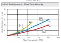
Things would be much simpler if all the manufacturers of these whiz-bang super duper residential filters would publish curves of face velocity versus pressure drop. Sizing to get the desired pressure drop then becomes real simple. Pick your pressure drop off the curve and get the corresponding face velocity. Multiply unit tonnage by 400 and divide the result by the face velocity in feet per minute, and you have the required area in square feet.

This type of information has been published for years by the manufacturers of filters for industrial and institutional use. Being the somewhat cynical jackass that I am, I sorta tend to think the lack of published information on consumer marketed filters is self serving in that such information, if accurate, would impact sales to people who are knowledgeable enough to notice that many of these filters have pressure drop levels high enough to have a definite negative impact on system performance.

Its worth mentioning that most large air handlers have filter racks arranged in a V formation. This allows the velocity thru the filters to be reduced without having to use a filter section that's larger than the unit itself. The same design can be applied to a residential air handler by adding a pair of filter tracks to the return duct in a V formation, or by using a single track which inclines the filter rather than placing it at 90 degrees to the airflow, thus allowing the use of a larger single filter.

IMO, the real root cause of static pressure problems on most residential systems is a lack of code enforcement on the original installation. Practices such as putting a box on the discharge of the air handler and going from there with a truckload of flex, or installing a return that's nothing more than a single stud space, or maybe 2 spaces, with a filter grille, are both situations in direct violation of hvac codes. Enforcing code provisions on max length of flex runs and verifying adequate return cross section would solve the majority of problems that are built in to systems at installation. An added benefit would be the majority of the jacklegs in the business would either learn to do proper installations (unlikely) or be run out of business.
 

fitter30

Well-known member
Joined
Jun 23, 2019
Messages
3,034
Location
Peace Valley,mo
A air filter in a furnace is only as efficient as the air flow through the space. Meaning how well all the air mixes and is picked up by the return then through the filter. Dirt in the duct is only there because it's to heavy for the air flow to move it. Supply grills get dirt not by dirt in the flow but by the tip speed causing turbulence and picking up dirt from the surrounding air. When the sun is shining through a window at a certain angle you can se the dirt particles floating and not really moving.
 
OP
S

SGKent

Banned
Joined
Feb 12, 2010
Messages
1,959
Location
Citrus Heights CA
If you double the filter face area, the resulting pressure drop will be less than half what it was previously. This is because, like most everything related to energy (in this case, the energy required to move air), required energy does not vary linearly with velocity. The energy increases faster than the velocity.

Things would be much simpler if all the manufacturers of these whiz-bang super duper residential filters would publish curves of face velocity versus pressure drop. Sizing to get the desired pressure drop then becomes real simple. Pick your pressure drop off the curve and get the corresponding face velocity. Multiply unit tonnage by 400 and divide the result by the face velocity in feet per minute, and you have the required area in square feet.

This type of information has been published for years by the manufacturers of filters for industrial and institutional use. Being the somewhat cynical jackass that I am, I sorta tend to think the lack of published information on consumer marketed filters is self serving in that such information, if accurate, would impact sales to people who are knowledgeable enough to notice that many of these filters have pressure drop levels high enough to have a definite negative impact on system performance.

Its worth mentioning that most large air handlers have filter racks arranged in a V formation. This allows the velocity thru the filters to be reduced without having to use a filter section that's larger than the unit itself. The same design can be applied to a residential air handler by adding a pair of filter tracks to the return duct in a V formation, or by using a single track which inclines the filter rather than placing it at 90 degrees to the airflow, thus allowing the use of a larger single filter.

IMO, the real root cause of static pressure problems on most residential systems is a lack of code enforcement on the original installation. Practices such as putting a box on the discharge of the air handler and going from there with a truckload of flex, or installing a return that's nothing more than a single stud space, or maybe 2 spaces, with a filter grille, are both situations in direct violation of hvac codes. Enforcing code provisions on max length of flex runs and verifying adequate return cross section would solve the majority of problems that are built in to systems at installation. An added benefit would be the majority of the jacklegs in the business would either learn to do proper installations (unlikely) or be run out of business.

that agrees totally with my online research. As a sidenote, the issue I have is that the HVAC unit sits in the garage backed up to a closet inside the house that is the only full door closet we have so it can't be converted (1400 sq ft 3/2 house), and the side of the unit is about 10" from the wall the duct goes thru to. A water heater and gas lines are on the other side of the HVAC system. There is very little room to play with for the return duct, unlike say in a house with the HVAC system in the attic or basement where the area is almost unlimited to add filters. If I increase the filter beyond the 20x25 that is there, the whole wall near the front door begins to look like a filter grille. With all the requirements for smoke detectors, an alarm and whole house fan we have, lights, and the one hallway ceiling return grille, adding another on the ceiling is not aesthetically acceptable either. The one thing you pointed out that might work would be to add a filter to the return cabinet at an angle and abandon the wall and ceiling filters. That might give enough surface area, I'll have to do the math to see what that would allow. The unit was really designed for an internal filter that sat in the base. Such a filter was designed to have a .10" wc resistance. That pretty much describes a fiberglass filter too. The concept of higher filtration was not thought of 30 - 40 years ago like it is today. Homes were looser, no one had air membrane wraps on homes, energy was inexpensive pretty much. The fact that the state of California now has a new code coming requiring manufacturers to post the resistance and MERV on all filters is an indication how far behind the curve the industry is. And yes, it is self serving. If a HVAC system life is reduced by 10 years because of a higher MERV filter the consumer doesn't even begin to think that the failure (or higher energy costs) were driven by the higher MERV filter they are using. We saw a thing last night on This Old House where they were showing a heat / inside-outside air transfer unit, and VOC / CO2 sensors that are designed to improve household air without a significant loss of energy. One can see that the whole industry has changes coming that will completely change how HVAC is handled. Adding better filtration is just one step. On a funny side - we have skunks around here that sometimes let loose. I can't imagine what people will do when their air exchange unit brings skunk scent into the house or the neighbor's leaf pile when it is burning. What will the next generation be that has AI sniffers on exchange air to be sure one doesn't fill the house with skunk scent at 2am from a skunk that was run over or attacked. :)
 

jobo1004

Well-known member
Joined
May 18, 2014
Messages
505
Location
Kansas City, MO
If you look at commercial filters they generally provide curves for pressure drop as a function of face velocity. For instance I've attached a curve for AAF's PREpleat M13, which is a MERV 13 filter. As you can see if you're stuck with a 1" filter, you've got to have a huge filter area in order to get the initial pressure drop down. Then obviously every day the unit runs, the filters load up and the pressure drop increases.
 

Attachments

  • Annotation 2019-11-25 154630.jpg
    Annotation 2019-11-25 154630.jpg
    20.6 KB · Views: 10
OP
S

SGKent

Banned
Joined
Feb 12, 2010
Messages
1,959
Location
Citrus Heights CA
the whole house fan has a set of louvers that seal with foam. Yes - there was a test done of both the house and the HVAC when the system was put in in 2005. It was very efficient but I don't recall the result numbers. I Tyveked it in 2003 - 2004 and sealed all the drywall to the pressure treated sill with foam as the siding was replaced, and also along the top plate to exterior drywall. The windows are all replaced and well sealed too. Other than vent fans, and places the wiring comes thru the top plate it is pretty tight. The home was built in 1979 and they didn't seal spots where the wiring passed thru the top plate back then. That is on my to do list. We have two terriers who go outside every few hours so there is always some air being exchanged. RH is usually less than 50% in the house.
 
To avoid these ads, REGISTER NOW!
Top Bottom