FULLSCALE302
Well-known member
- Joined
- Apr 8, 2014
- Messages
- 130
Been looking around here for a while, but never got around to posting until now.
Long story short, my wife who is a graphic designer has been helping someone who owns a plasma table how to use his computer programs to design things. She is being compensated by items cut on his table. Sounded like the perfect time to build the welding table I've always wanted...
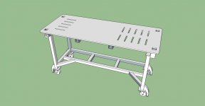
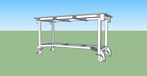
I don't have a huge shop/garage. It's 14x38' inside so I'm limited in table width so I can still easily get a car in beside it to work around it. I decided to go with 30x74" for the new table, the same length as what I have but just a couple inches wider. The top will be 1/2" thick. 2-1/2" 1/4" wall square tubing for anywhere there is a receiver tube and 2" square tubing for the rest.
Unless someone convinces me otherwise, I'd like to go with 5/8" slots as that's the biggest clamping kit I can find locally in southern Ontario at a reasonable price (http://www.busybeetools.com/products/clamping-kit-1-2in-52-pcs.html).
Is there anything wrong with the design of my slots in the table? My thoughts are to use the right side for smaller jobs, and anything too long for that area can extend over and be clamped down on the left side. This way I'd still have a nice large smooth area in the middle as this will also serve as my regular work bench.
Any advice or input would be greatly appreciated!
Long story short, my wife who is a graphic designer has been helping someone who owns a plasma table how to use his computer programs to design things. She is being compensated by items cut on his table. Sounded like the perfect time to build the welding table I've always wanted...
I don't have a huge shop/garage. It's 14x38' inside so I'm limited in table width so I can still easily get a car in beside it to work around it. I decided to go with 30x74" for the new table, the same length as what I have but just a couple inches wider. The top will be 1/2" thick. 2-1/2" 1/4" wall square tubing for anywhere there is a receiver tube and 2" square tubing for the rest.
Unless someone convinces me otherwise, I'd like to go with 5/8" slots as that's the biggest clamping kit I can find locally in southern Ontario at a reasonable price (http://www.busybeetools.com/products/clamping-kit-1-2in-52-pcs.html).
Is there anything wrong with the design of my slots in the table? My thoughts are to use the right side for smaller jobs, and anything too long for that area can extend over and be clamped down on the left side. This way I'd still have a nice large smooth area in the middle as this will also serve as my regular work bench.
Any advice or input would be greatly appreciated!