To avoid these ads, REGISTER NOW!

floor truss removal in a barn style shop

dirty30

Member
Joined
Oct 19, 2011
Messages
17
You guessed it, making room for a Bend-Pak XPR 10 Asymmetrical lift in my shop.

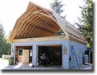
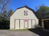
Shop 30X30 was built in 2002 by the previous owner for mainly storage for his Antique store business, so he needed attic space for items..problem is

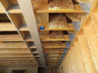
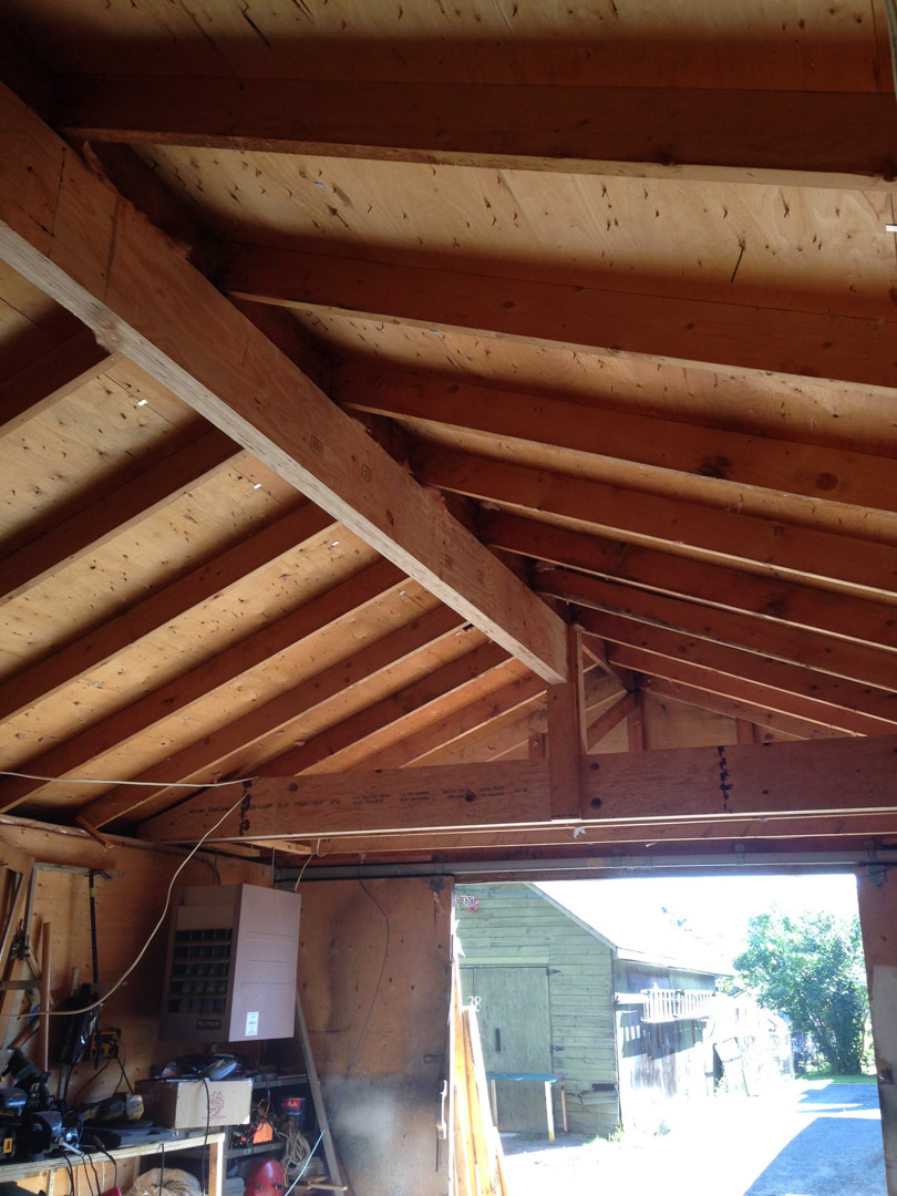
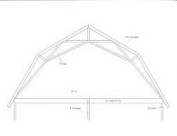
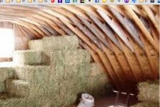
It's a gambrel (barn style) roof with attic room trusses, semi finished with 5/8" OSB flooring. Bottom level cement floor to bottom of upper floor trusses is 9'9", and space from the top of the second floor trusses to the bottom of the top chord(attic space)is 7' 1- 1/4" which is plenty of room for the lift 16' + feet. Plus another 10" when you remove the floor truss itself.

How do I remove the second floor trusses in the area where I install the lift and still maintain structure strength? I contacted a structural engineer about the issue and he made a couple of suggestions. One, he wanted to run a LVL beam underneath each side of the opening where the trusses are to be removed to support the floor, full length end to end. Then, he wanted to put a LVL/steel beam on the exterior wall on each side the same length of the opening in would be removing inside and tie both beams together with tension rods, essentially supporting the side load from pushing out the exterior walls at the top sill plate.

I've already removed the 5/8" OSB flooring in between the trusses where the opening would be, framed up the opening on the second level with 2x4's 16" OC and sheathed the wall with 1/4" Plywood. I also laid 1/4" plywood in the attic level. Added 3 sistered 10"x30' on each side of the opening one way 6 total, and plan on running 3 sistered the opposite on each side once the trusses were removed. The framed in wall on the second floor bottom plate is directly over the sistered 10"X30's.

His second option was to essential re-truss the inner structure with a 9/12 pitch of 10"X2"sistered to the existing trusses on each side, anchored together with bolts to the existing trusses over just where the new opening would be and anchoring them at the top to a new ridge beam and the bottom would sit on the sill plate. Essentially putting a normal pitched truss inside of a gambrel style truss..make any sense?

How would you solve this problem if it were you?

I've attached pics of the dilemma.
 

Attachments
  • IMG_0348.JPG
    IMG_0348.JPG
    139.7 KB · Views: 79
  • IMG_0358.JPG
    IMG_0358.JPG
    111.5 KB · Views: 81
  • IMG_0357.JPG
    IMG_0357.JPG
    118 KB · Views: 78
  • IMG_0352.JPG
    IMG_0352.JPG
    120.3 KB · Views: 80
  • IMG_0351.JPG
    IMG_0351.JPG
    128.5 KB · Views: 125
  • IMG_0354.JPG
    IMG_0354.JPG
    132.9 KB · Views: 90
  • IMG_0350.JPG
    IMG_0350.JPG
    128.1 KB · Views: 89
Last edited:
To avoid these ads, REGISTER NOW!

theoldwizard1

Well-known member
Joined
Feb 22, 2011
Messages
43,344
Location
SE MI
Then, he wanted to put a LVL/steel beam on the exterior wall on each side the same length of the opening in would be removing inside and tie both beams together with tension rods, essentially supporting the side load from pushing out the exterior walls at the top sill plate.
Most people don't understand that ceiling/second floor joist do 2 functions. Support the floor and prevent the sides from bowing out from the downward/outward load of the roof.

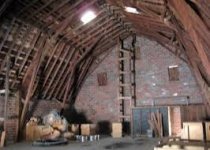
If you really want that lift, you are going to have to remove the existing gambrel roof and replace it with typical pitched roof made with scissors or vaulted parallel trusses.

I'm sure a gambrel roof without any ceiling level joists could be designed, but it would be a "one off" and probably pretty expensive.
 
OP
D

dirty30

Member
Joined
Oct 19, 2011
Messages
17
In theory, I understand what he was trying to accomplish by putting the beams on the exterior walls. I knew that the outward forces would want to push the top sill outwards based on that particular truss design and the floor joists are under tension. This wouldn't be a problem if the roof was a scissor style truss, but replacing the roof is not a option.

You can get a scissor style truss design in a gambrel roof which I wish this was designed for originally, but I'm working with what I've got. I just thought there maybe an alternative that I haven't thought about but based on what I'm finding, I'm kinda stuck.
 

theoldwizard1

Well-known member
Joined
Feb 22, 2011
Messages
43,344
Location
SE MI
Added 3 sistered 10"x30' on each side of the opening one way 6 total, and plan on running 3 sistered the opposite on each side once the trusses were removed. The framed in wall on the second floor bottom plate is directly over the sistered 10"X30's.
Are you referring to those board nailed flat to the under side of the joists ? Those are pretty useless for load carrying in that orientation. "Sistering" means adding a second (or third) board PARALLEL and directly attached to the first board like the joist over the center beam in the picture below.

Sistering_Joists.jpg


You are also assuming the studs in the second floor area are properly attached to the rafters and joists below and sized properly to take up the roof load. My eyeball says they are not installed in a way to be "load carrying".

If you do put proper beams in there under each second floor wall (probably steel so they don't hang down too far, with steel posts at each end) you would only solve half of the problem, the vertical load from the roof. There is still some horizontal load on the side walls. The roof rafter appear to be 2x4s (2x6s?). You would need something like a 2x4 connecting each rafter on the upper half of the roof to the corresponding rafter on the bottom half of the roof. This means cutting the plywood on the second floor walls lower so that new piece could be installed.

Run this idea past your engineer and ask him to work up some load calculations.
 

theoldwizard1

Well-known member
Joined
Feb 22, 2011
Messages
43,344
Location
SE MI
I found this one. It is steel ! I don't like the proportions of the upper and lower roof decks or the angles.

60170d1392150913t-gambrel-roof-steel-roof-insulation-vaulted-truss.jpg


All of the other designs I have found still have a joist connecting the 2 walls.
 

larry_g

Well-known member
Joined
Apr 28, 2007
Messages
16,900
Location
oregon
First thought that comes to mind is to extend the front or back wall to make another bay to install the lift in. It also looks as if you have a drive around the left of the building. Could you add a door in the sidewall so that you could enter parallel to the back wall and parallel to the trusses. That way you would have to alter fewer trusses and have the back wall that carries 1/2 the load already in place. Then structure parallel to the back wall with a header over the door, one on the opposite wall and run girts between the existing trusses to take the load to the back wall and the new structure parallel to the back wall. More like a 'bent' in a traditional barn.

lg
no neat sig line
 

Texsun

Well-known member
Joined
Mar 23, 2012
Messages
148
Follow the advice of the structural engineer, have signed drawings as well, you will have the best potential for a successful insurance claim should you need it.
 

joe_padavano

Well-known member
Joined
Feb 26, 2011
Messages
1,788
Location
Northern VA
I found this one. It is steel ! I don't like the proportions of the upper and lower roof decks or the angles.

60170d1392150913t-gambrel-roof-steel-roof-insulation-vaulted-truss.jpg


All of the other designs I have found still have a joist connecting the 2 walls.

It is certainly possible to design a truss like this in either wood or steel. The depth (width?) of each side will depend on the angles and load (winds, snow, roofing, etc). This is not an easy truss to design, but it's certainly within the realm of what's possible. Design of a truss like this MUST be done by an engineer who fully understands the loads and application.
 

Denwood

Well-known member
Joined
Sep 22, 2014
Messages
4,224
Location
Thunder Bay, Ontario, Canada
Check my build thread (signature). Ridge beam and cross beams will give you full height over the hoist.

I'd also consider the scissor truss idea. Your engineer should be able to provide a retrofit design where both sides of the affected trusses are clad (both sides) with plywood, and framed in the new scissor truss profile. We did exactly that with 50 foot trusses in our business space. A "window" 16-18 feet should be plenty.

ridge3.jpg
 
Last edited:
OP
D

dirty30

Member
Joined
Oct 19, 2011
Messages
17

Attachments

  • gambrel scissor truss barn.jpg
    gambrel scissor truss barn.jpg
    11.9 KB · Views: 33
  • gambrel scissor truss #2.jpg
    gambrel scissor truss #2.jpg
    10.3 KB · Views: 29
  • scissor truss #3.jpg
    scissor truss #3.jpg
    9.5 KB · Views: 35
  • modified gambrel truss.jpg
    modified gambrel truss.jpg
    6 KB · Views: 24
  • gambrel scissor truss.jpg
    gambrel scissor truss.jpg
    3.4 KB · Views: 23
  • gambrel scissor truss #1.jpg
    gambrel scissor truss #1.jpg
    7.8 KB · Views: 27
To avoid these ads, REGISTER NOW!

theoldwizard1

Well-known member
Joined
Feb 22, 2011
Messages
43,344
Location
SE MI
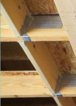
Never seen joist hangers installed like that.
If you are referring to these joist hangers, I agree. !

attachment.php


attachment.php


They aren't holding the joists, they are holing the blocking between the joists !
 

Attachments

  • Capture.JPG
    Capture.JPG
    31.5 KB · Views: 58
OP
D

dirty30

Member
Joined
Oct 19, 2011
Messages
17
Are you referring to those board nailed flat to the under side of the joists ? Those are pretty useless for load carrying in that orientation. "Sistering" means adding a second (or third) board PARALLEL and directly attached to the first board like the joist over the center beam in the picture below.

Sistering_Joists.jpg


You are also assuming the studs in the second floor area are properly attached to the rafters and joists below and sized properly to take up the roof load. My eyeball says they are not installed in a way to be "load carrying".

If you do put proper beams in there under each second floor wall (probably steel so they don't hang down too far, with steel posts at each end) you would only solve half of the problem, the vertical load from the roof. There is still some horizontal load on the side walls. The roof rafter appear to be 2x4s (2x6s?). You would need something like a 2x4 connecting each rafter on the upper half of the roof to the corresponding rafter on the bottom half of the roof. This means cutting the plywood on the second floor walls lower so that new piece could be installed.

Run this idea past your engineer and ask him to work up some load calculations.

If you look at picture one of the rafters, you can see the lighter colored board in front and some tie plates attached to it, that's where the 2X10" boards are sistered together, there are 3 of them tied together with engineered fasteners. The plan was to run two more in the opening where the floor trusses will be removed and tie them to the joist hangers that are already in place.

I know at his point the second floor area needs to be attached with anchors to tie it in to the top attic truss chord and the bottom floor truss chords. As for right now it's nailed in, but anchors will be installed. It's really not a load carrying bearing wall it was made to frame in the second floor open area for heat and insulation.

The engineer was planning on putting in (2) either steel beams or LVL directly under the existing straight attic room truss chord and floor truss. At least 10"-12" spanning the full length of the structure, from the front wall to the back wall. He would either use columns inside the back wall and joist hanger on the front where the beam would attach to the door header. This would sufficiently take care of the downward load.

The main concern was horizontal load spread, pushing the walls out. This was where I was looking for other engineering options..I wasn't crazy about a full length LVL or steel beam going the entire span on the outside of the wall to hold it together.

The straight 2X4 beam you suggest ( the engineer actually suggested 2X10" full length, from the top point mounted to a newly installed ridge beam, to the top sill plate at the bottom, at a 45 degree angle, sandwiching the existing gambrel truss, and attached with bolts or bolt plates.) This idea was brought up but would be very costly in labor and lumber.
 
Last edited:
OP
D

dirty30

Member
Joined
Oct 19, 2011
Messages
17
Never seen joist hangers installed like that.

The joist hangers are in place to tie in the end of the open floor truss area once the trusses are removed. There will be (2) more full length 2X10" boards attached to the ends of the floor truss, inside, and the smaller spacer boards tied together with engineered fasteners. The horizontal side tension will be taken up by another method. This was done just to keep the floor trusses somewhat even inside. The ends of the full length boards, once installed, will be anchored to the ends of the opposite sistered, unaltered floor truss with joist hangers.
 
Last edited:
OP
D

dirty30

Member
Joined
Oct 19, 2011
Messages
17
Ignore the boards mounted flat underneath the floor truss. They were there to spread the load out when I had some lolly columns underneath. They are coming off.
 

theoldwizard1

Well-known member
Joined
Feb 22, 2011
Messages
43,344
Location
SE MI
If you look at picture one of the rafters, you can see the lighter colored board in front and some tie plates attached to it, that's where the 2X10" boards are sistered together, there are 3 of them tied together with engineered fasteners.
Okay I see that now.
attachment.php


The plan was to run two more in the opening where the floor trusses will be removed and tie them to the joist hangers that are already in place.[
Let's get our terminology correct. The truss is the whole assembly, before the roof decking is applied. The bottom board that spans side load bearing wall wall to side load bearing wall that the second floor decking is attached to is called the bottom chord.

I'm sorry I just don't understand what your are saying when you say "run two more in the opening where the floor trusses will be removed". I assuming you mean the bottom chord of the truss. Why are you putting sistered 2x10s where you just removed the bottom chord. I just can't visualize it.

The engineer was planning on putting in (2) either steel beams or LVL directly under the existing straight attic room truss chord and floor truss. At least 10"-12" spanning the full length of the structure, from the front wall to the back wall. He would either use columns inside the back wall and joist hanger on the front where the beam would attach to the door header. This would sufficiently take care of the downward load.
Exactly what I was recommending.

The main concern was horizontal load spread, pushing the walls out. This was where I was looking for other engineering options.
In THEORY (in other words, no calculation have been done) if a collar tie is installed at the peak ...

attachment.php


... and at the "knee" between the upper and lower roof deck and at the connection between the lower roof deck and the remainder of the bottom chord.

attachment.php


I wasn't crazy about a full length LVL or steel beam going the entire span on the outside of the wall to hold it together.
With the ties installed at the peak and each "knee" I am think that there would be addition outward load so there would be no need for a beam on the outside.
 

Attachments

  • Capture.JPG
    Capture.JPG
    41.3 KB · Views: 41
  • Capture2.JPG
    Capture2.JPG
    49.5 KB · Views: 343
  • Capture3.JPG
    Capture3.JPG
    24.8 KB · Views: 39
Last edited:
To avoid these ads, REGISTER NOW!
Top Bottom