To avoid these ads, REGISTER NOW!

Foot switch wiring to dc motor

Ebaby35

Member
Joined
Apr 14, 2018
Messages
17
Location
Orange county, Ca
Ok I'll got my bead roller almost all wired up, except for the momentary foot switch. Does the foot switch connect to dc control board? The foot switch I have can work by plugging it into the wall and the bead roller then plugging into it. So every time I press pedal the machine turns on and runs to whatever settings I have. I would like to wire different if possible to where when I turn the on switch on and my little green light turns on showing machine is receiving power and then when I press pedal it works.
 
To avoid these ads, REGISTER NOW!

Stuart in MN

Well-known member
Joined
Sep 8, 2005
Messages
23,486
Location
Minneapolis
You need to tell us what brand/model motor and controller you have first, before anyone can hazard a guess on how to connect the switch.
 
OP
E

Ebaby35

Member
Joined
Apr 14, 2018
Messages
17
Location
Orange county, Ca
Hi sorry I running a Dayton 4z723a gear motor 1/12 hp 90v dc motor with a kbmg-21d controller. So far I have a on/off switch, potentiometer connected and working. I would like to connect a forward/reverse drum switch and have this controlled to start when I press the foot pedal. I have a light too that I would like to turn on when the on/off is turned on.
 

walta

Well-known member
Joined
Jan 13, 2017
Messages
2,322
Location
Dutzow Missouri
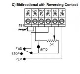
This should work see photo

The lamp cannot be an LED it must be incandescent as an LED would only light in one direction not both.

If you use a 12 volt lamp it will need a resistor in series, the value will change based on the lamp.
 

Attachments

  • b.jpg
    b.jpg
    16.6 KB · Views: 54

laser3kw

Well-known member
Joined
Nov 17, 2012
Messages
7,276
Location
northen IL
This should work see photo

The lamp cannot be an LED it must be incandescent as an LED would only light in one direction not both.

If you use a 12 volt lamp it will need a resistor in series, the value will change based on the lamp.

That's a good setup Walta but the lamp bothers me. I would test the circuit without it first and then insert it. I see the lamp as a low resistance parallel resistance circuit (shunt), that will, in effect, neutralize the usefulness of the pot. If you put a large enough resistor in line with the lamp, the lamp will not light.
I would try a LED from "sig" to "com". That will not shunt current around the pot. If that doesn't work maybe a LED on each output leg of the switch. Caution here is that each LED will have to be inserted carefully polarity wise.
 
Last edited:
OP
E

Ebaby35

Member
Joined
Apr 14, 2018
Messages
17
Location
Orange county, Ca
Going to try what Walt's suggested but without the light which isn't a must just thought it would look cool. Thanks for your help too
 
OP
E

Ebaby35

Member
Joined
Apr 14, 2018
Messages
17
Location
Orange county, Ca
Quick question does the drum switch have to be run through the dc drive? Could I have it connected right before the motor and connect to to the power coming out from dc controller?
 

walta

Well-known member
Joined
Jan 13, 2017
Messages
2,322
Location
Dutzow Missouri
A “drum switch “may not work in my circuit as generally they have big heavy contacts to handle the full current flowing to a large motor 600 volts and 50 amps, the low voltage and current in this circuit may not reliably flow thru the heavy contacts. But maybe we are not talking about the same thing.

A small switch rated for low voltage and current would be more reliable in this circuit.

https://www.amazon.com/dp/B006LU9LVC/?tag=atomicindus08-20

or something bigger like this one.

https://www.amazon.com/dp/B001TJ8QCA/?tag=atomicindus08-20

I think the lamp will not be a problem as it is connected to the ground and one of the 15 volt power supplies, as long as the lamp draw is under 300 milliamps.

I do not like to see anything between the control board and the motor. Because if the switch is operated while the motor is under power it is likely to damage the control board.


Walta
 

laser3kw

Well-known member
Joined
Nov 17, 2012
Messages
7,276
Location
northen IL
I do not like to see anything between the control board and the motor. Because if the switch is operated while the motor is under power it is likely to damage the control board.
x2
sound advice :thumbup:
 
To avoid these ads, REGISTER NOW!
OP
E

Ebaby35

Member
Joined
Apr 14, 2018
Messages
17
Location
Orange county, Ca
Ok so somehow I blew my fuse. But you guys have be a lot of help. These are all the things I need to have wired.
I have a on/off switch, a potentiometer for adjusting,) speed, a forward/brake/reverse switch and a momentary foot pedal which plug into wall and then the power cord from dc converter plugs into that. I have most wired up but can't get it all running and the setup I want. I just want to plug it in then be able to turn the on/off switch on to power it then set the speed and then direction then press pedal to go. Right now the on off switch cobtrols power to the motor but not to the dc controller. Its only when i press the pedal that power goes to co troller
 

dogdog

Well-known member
Joined
Nov 15, 2011
Messages
12,711
I think if I read the post correctly you have the foot paddle that controls the AC on/off to the controller, a switch that controls the direction of the motor and the variable resistor hooked up as in that diagram to control that speed ? Not sure if that is a great setup...

I could be completely wrong on this...

So you wanted to be able to turn AC to the controller on/off with a regular AC toggle type switch... and the foot paddle to control the on/off of the motor, a separate SPDT center off toggle switch to control the direction, and a variable resistor pot to control the speed?

-->This is easy just rearrange your current components and add an on/off switch for ac...
This one is easy and can utilize what you current have I think...

1) Just take off your current AC paddle that turns off the AC power to the controller, add a regular switch... any switch... that fits the power requirement of cause, it shouldn't draw that much amp as long as it is AC rated.

2) take a look at the diagram on post #4 or your controller's manual. hook up would be the same, except that at the center pin of that reverse switch and the end that is to the variable resistor... you break the contact and add that foot paddle...


attachment.php


Or are you looking for ?

change the current AC on/off with a switch.
add a food paddle that can have variable speed with a separate SPDT center off for direction?

--> this you'll needed to hunt for that special paddle with a variable resistor build in... they do exist.... I know my welding machine uses it.. Not too sure where you would source the component of that...essentially this one is the variable resistor and build into the foot paddle I think... with an extra on/off that is build into the paddle... so you'll still needed that SPDT center off switch for dir control.

or
change the current AC on/off with a switch
have a foot paddle that can do reverse / forward (one of those double paddle setups)
and have a variable resistor some where to control the speed.... these type of foot paddles I have seen but pretty expensive I think....
 
Last edited:

dogdog

Well-known member
Joined
Nov 15, 2011
Messages
12,711
This should work see photo

The lamp cannot be an LED it must be incandescent as an LED would only light in one direction not both.

If you use a 12 volt lamp it will need a resistor in series, the value will change based on the lamp.

Not sure, I would use two LEDs even better, one indicate forward, the other indicate reverse all in the same setup.


................

I do not like to see anything between the control board and the motor. Because if the switch is operated while the motor is under power it is likely to damage the control board.


Walta

Can you explain this... I am interested in learning.....
 
OP
E

Ebaby35

Member
Joined
Apr 14, 2018
Messages
17
Location
Orange county, Ca
Just want a switch that give whole unit power. Then a switch to toggle forward and reverse and knob to set speed. And a foot paddle that when machine is powered when pressed will go in whatever direction and speed I have preset. Maybe I got the wrong foot pedal because I first plug it into wall and then the power cord from drive go into it. Right now I messed up the dc controller up now when I plug it in it instantly trips my breaker
 

dogdog

Well-known member
Joined
Nov 15, 2011
Messages
12,711
I think this is what you needed... pretty sure that other on/off AC switch is simple for you. that you don't needed a diagram for it.

Sorry I don't have the exact same controller you have so ... this should work for you...
 

Attachments

  • b2.jpg
    b2.jpg
    25.2 KB · Views: 48
Last edited:

walta

Well-known member
Joined
Jan 13, 2017
Messages
2,322
Location
Dutzow Missouri
Can you explain this... I am interested in learning.....

This is a DC motor when you apply power a DC motor it builds a magnetic field around the motor. If anything interrupts the flow of power to the motor the magnetic field collapses the energy stored in the magnetic field is absorbed by the coils of the motor. This energy will find a complete circuit! If this energy cannot flow as current it becomes high voltage. So if you put a switch between the control board and the motor when the switch opens the magnetic field collapses the voltage across the switch builds until it arcs across the switch this high voltage spike goes thru the control board and could damage the semiconductors and may destroys the control board.

Let’s say the magnetic field has 1 watt of energy that it will dissipate. Without the switch the flow could be 5 amps at .2 volts= 1 watt but with the switch it could be 0.0001 amps at 10,000 Volts = 1 watt.

Walta
 
Last edited:

dogdog

Well-known member
Joined
Nov 15, 2011
Messages
12,711
Oh that.... yes ok... I remember similar that in the good old magneto class.... Thx.. nvm sorry some times I read things wonky.

Yea the op have one of those AC plugin foot paddle that interrupt the whole AC to the unit to control the motor, not too sure if that is a good idea.... if I didn't read that wonky...
 

walta

Well-known member
Joined
Jan 13, 2017
Messages
2,322
Location
Dutzow Missouri
Ok so somehow I blew my fuse. But you guys have be a lot of help. These are all the things I need to have wired.
I have a on/off switch, a potentiometer for adjusting,) speed, a forward/brake/reverse switch and a momentary foot pedal which plug into wall and then the power cord from dc converter plugs into that. I have most wired up but can't get it all running and the setup I want. I just want to plug it in then be able to turn the on/off switch on to power it then set the speed and then direction then press pedal to go. Right now the on off switch cobtrols power to the motor but not to the dc controller. Its only when i press the pedal that power goes to co troller

It is very bad thing when fuses blow in this type of circuit.
Let’s hope it works with a new fuse.
Please draw a diagram of how you have it hooked up.

Walta
 

laser3kw

Well-known member
Joined
Nov 17, 2012
Messages
7,276
Location
northen IL
I think this is what you needed... pretty sure that other on/off AC switch is simple for you. that you don't needed a diagram for it.

Sorry I don't have the exact same controller you have so ... this should work for you...
Yes! as others have said - do not interrupt the incoming AC. The diagram with foot switch in the "stop" line will work
 
OP
E

Ebaby35

Member
Joined
Apr 14, 2018
Messages
17
Location
Orange county, Ca
Well now I need to have the dc controller looked at or figure out if I broke it. I took all the wire and connections off and now the led light doesn't even turn on and immediately after plugging in it trips my breaker. So not sure if my dumb *** destroyed it.
 

laser3kw

Well-known member
Joined
Nov 17, 2012
Messages
7,276
Location
northen IL
I have a on/off switch, a potentiometer for adjusting, speed, a forward/brake/reverse switch and a momentary foot pedal which plug into wall and then the power cord from dc converter plugs into that.
post up some pics? with wiring? :dunno:
obvious, does it smell burnt / smoke?
I am trying to read between the lines here.... did you hook your 120v foot switch to the "for" and "rev" terminal screws? Or did hook it up between the controller DC output and the DC motor?
I don't have a good feeling that the controller liked the foot switch and is ****-ed.
 
Last edited:
OP
E

Ebaby35

Member
Joined
Apr 14, 2018
Messages
17
Location
Orange county, Ca
The foot switch was plugged into wall and the power cab that came out of my dc controller plugged into the foot cord. Doesn't smell burnt
 
To avoid these ads, REGISTER NOW!
Top Bottom