To avoid these ads, REGISTER NOW!

Frankenpressor build

1930artdeco

Well-known member
Joined
Dec 28, 2010
Messages
1,099
Location
Lynden, Wa
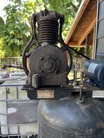
Ok, hoping to make this a small build thread. But I just mocked up my 41 Wayne compressor with my NOS Leeson 1.5 HP electric motor on top of my 87 Sanborn 60 gal. upright tank. Had to have an adapter plate made to get the pilot to bolt up. So far everything seems to bolt up. This weekend hoping to pour the slab and install the following weekend!

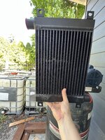
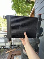
Then I will have to figure out the plumbing. So far I am leaning of going from the tank to a ****** cooler and then copper drops (x2) with drains at the bottom of the drops. Then copper into the garage with two ports for tools inside and one outside.

Mike
 

Attachments

  • IMG_9875.jpeg
    IMG_9875.jpeg
    836.7 KB · Views: 150
  • IMG_9874.jpeg
    IMG_9874.jpeg
    733.9 KB · Views: 139
To avoid these ads, REGISTER NOW!

larry_g

Well-known member
Joined
Apr 28, 2007
Messages
16,872
Location
oregon
Do you have the specs on that compressor head? Is spec'ed to run with a 1.5 hp motor?

lg
no neat sig line
 

cannuck

Well-known member
Joined
Nov 30, 2021
Messages
4,602
Location
Rural SK
I will be a bit surprised if that 2 stage head will run on 1.5 HP, but if it does I think you will have a really nice setup. What I strongly suggest you do is use a clamp on ammeter to measure load during startup and particularly at end of run when pressure is reaching setpoint. The inrush might force you into a motor starter to handle the momentary overload but at the HP end of the cycle you want to finish as close to amperage draw on the motor nameplate as you can get. Your 2 variables will of course be max press setpoint (that could go quite high with 2 stage head) and motor pulley size. I have 4 2HP compressors (2 screw and 2 recip) and you can get a LOT of work done with that size (IMHO entry level for low air use shop).
 
OP
1

1930artdeco

Well-known member
Joined
Dec 28, 2010
Messages
1,099
Location
Lynden, Wa
According to the original spec sheet it used a 1.5 HP motor which is why I went with this motor. Otherwise I would have gone with a larger motor. I just didn't want to over power the compressor. I will only be going to 100 psi, so not taxing the pump or tank at all. Originally I believe it went to 125 psi with a horizontal 60 gal. According to a pulley calculator I had to go with a 4" pulley in order to keep the pump speed down to around 800 RPM, which is close to the original speed. The original Sanborne motor is the 3450 RPM style so can't use it. I might be able to plug it in with a make shift cord to test it out before I get it hard wired into the house.
 
OP
1

1930artdeco

Well-known member
Joined
Dec 28, 2010
Messages
1,099
Location
Lynden, Wa
Ok here is what I am thinking as far as filters, dryers, etc...

1) Compressor to aftercooler and drain then into the tank.
2) Tank to another aftercooler/****** cooler (may be overkill?) and a drop or two.
3) oil Seperator/water trap/regulator
4) main line with a drop/water trap at each line connector (there will be 3 max)

I am not a shop, just a hobbyist. I will be using air for the occasional paint job (small stuff), grinding/cutting tool for some sheet metal work. Does my list make sense or am I overkilling/overthinking the problem?

Thanks,

Mike
 
OP
1

1930artdeco

Well-known member
Joined
Dec 28, 2010
Messages
1,099
Location
Lynden, Wa
Now that I am moving forward with the build I am starting to look at plumbing. I am thinking 3/4” copper with three exit points-each with a water trap. The length is 50ft max-50 if you count the bends and turns. I am thinking of using standard coupling for air hoses-3/8 or 1/2”.

Not planning on a blaster right now. If I get one it will be a portable style from HF with a small tip. Will the 3/4” hold the pressure (100psi) or do I need 1/2”?
 

Steve W.

Well-known member
Joined
Mar 27, 2019
Messages
1,244
Location
Southwest oHIo
With a blaster, you need volume, just as much as you need pressure, I don't think there will be any difference between the 1/2" and 3/4" in your application other than cost up-front.

I have a single-stage vertical IR compressor/tank at my place. I have 1/2" copper lines running in a broad "U" around the room. Supply is in the middle of the "U". On one leg, there is a drop near the "wet bench", which has the parts washer tank, ultrasonic cleaner and shop sink. It continues to the front wall, where there is the retractable hose reel at the overhead door, and a separate connector just below the reel. On the other leg of the "U" are the blaster cabinet and a connector near the drill press. So far, I have had no problems with the system keeping up with anything I am doing.

For my install, each of the drops has a 1/4-turn ball valve, then a "T", then another 1/4 turn ball valve. The side leg of the "T" has a 45° elbow and a quick-connect. The length of pipe between the "T" and the lower ball valve is a drip leg. Each of the drops has a "T" off the main line that points UP, then a couple of 90s to take it down the wall. This minimizes moisture in each drop.

I am still wanting to use a cooler (like you mentioned) between the compressor and tank, that will likely remove the last bit of moisture that I am getting now, which isn't much at all.

.
 

customh

Well-known member
Joined
Feb 18, 2013
Messages
562
Location
East Bethel, MN
Now that I am moving forward with the build I am starting to look at plumbing. I am thinking 3/4” copper with three exit points-each with a water trap. The length is 50ft max-50 if you count the bends and turns. I am thinking of using standard coupling for air hoses-3/8 or 1/2”.

Not planning on a blaster right now. If I get one it will be a portable style from HF with a small tip. Will the 3/4” hold the pressure (100psi) or do I need 1/2”?

Pressure won't be a concern- worst case 3/4" copper working pressure is 495psi.

Do what @Steve W. said. I'd add that all of the copper compressed air piping I've done has been Type L. You can't go wrong with bigger pipe but if you do as Steve says AND make a complete loop rather than just a U you'll never have supply volume issues with 1/2" on that size compressor.
 

Steve W.

Well-known member
Joined
Mar 27, 2019
Messages
1,244
Location
Southwest oHIo
... if you do as Steve says AND make a complete loop rather than just a U you'll never have supply volume issues with 1/2" on that size compressor.
I have seen the loop suggested for some larger installations with possibly several users, but in my small area, the longest run is about 25', and I am usually the only one there. In MY case, it just did not make sense to continue past the overhead door, go around a corner, continue over all the shelving, go around another corner, and end up at the drill press.

Just one more suggestion for the OP: if you are going to be soldering copper for your lines, keep things managable by putting unions in the line every so often. That way, you can separate the line into sections, instead of disassembling the whole thing. Part of my inspiration for that idea was that I was doing the install by myself. It was MUCH easier to lift sections into place.

.
 
OP
1

1930artdeco

Well-known member
Joined
Dec 28, 2010
Messages
1,099
Location
Lynden, Wa
Thanks Steve, I didn't understand/visualize what you had done until I googled a few pics and now I understand/and can visualize your set up. I am slowly forming how to build this in my head and am now looking at where to buy the Seperators/filters etc. Where does everyone get their parts? Is there a 'main' store that people use? I don't 'Home depot' special stuff but I can't see myself buying 3-5 filters at $500 ea. for my situation. So far Type M copper is $40 a 10 ft. section and I will need at least 10 factoring in cutting some down and a few bends and drops.
 

Steve W.

Well-known member
Joined
Mar 27, 2019
Messages
1,244
Location
Southwest oHIo
So far Type M copper is $40 a 10 ft. section and I will need at least 10 factoring in cutting some down and a few bends and drops.
You looking at 1/2" or 3/4"? Either way, you are getting raped. Just checked Menards (my usual go-to here), 1/2" M is $18.58 (before the 11% rebate) and 3/4" M is $26.98. Have not checked at Home Depot or Lowe's.

If you were looking for Type L (not really necessary), the 1/2" is 22.53, the 3/4" is $41.25.

I did not keep track of prices much when I installed mine (about 10 years ago), I did compare copper / galvanised / black pipe for ease of installation as well as overall cost, copper won. I decided that 1/2" would suffice for my shop, then just purchased the parts. Most likely made a few extra trips to get items I may have overlooked, but Menards is only 4 miles down the road. It's just another mile to Home Depot and Lowe's, which are across the street from each other.

.
 
OP
1

1930artdeco

Well-known member
Joined
Dec 28, 2010
Messages
1,099
Location
Lynden, Wa
Yeah I know, I checked lowes, HD and True Value all the same. I may go to Canada and see what it is there.
 
OP
1

1930artdeco

Well-known member
Joined
Dec 28, 2010
Messages
1,099
Location
Lynden, Wa
Well it is now bolted to the pad outside (covered up with a tarp for now) and I will try and get to the shed this weekend. Got 60 feet of 3/4" copper pipe $$$$. Next up is an aftercooler (x2?) then the filters.
 

Sumboodie

Well-known member
Joined
Mar 20, 2021
Messages
10,663
Location
AK
Aftercooler is overkill in many applications for home jobber.

Only one maybe would benefit is if doing alot of sandblasting.
Painting is fairly low air usage.

I've been limping along with a 25 gallon oilless, like 8cfm maybe. Originally set to max at 125psi but I cranked it to 140 to be able to air tires. And even still I'll have get it to kick in to fully fill truck, trailer or forklift tires (100-120psi)

If only starts spitting water after it's gotten roasting hot, like been running nearly non stop for 45+ mins.
This is with a water seperator, just the air is so warm the moisture carries through that.

If the compressor is keeping up fine without running constant the air shouldn't be getting all that hot and a seperator would handle it fine.
Having a 2nd tank would help too.

My old setup had the compressor in the shed, just a crappy like 10 cfm 60 gallon Home Depot base model and about 80ft of 1" like buried in conduit (maybe was 3/4", been a while) to the garage where it fed the little 25 gallon compressor I'm using now.
I'd get a cup or two of oil and water from the 60 gallon tank the 2-3x a year I drained it.

Never got any water beyond that.
 
Last edited:
OP
1

1930artdeco

Well-known member
Joined
Dec 28, 2010
Messages
1,099
Location
Lynden, Wa
What kind of silver solder should I use? I went to the welding store and it is really expensive for the sticks of it-like $80 for 7 pcs. There is a roll of it at The depot for $50-does it matter or is all the same?
 

T444e

Well-known member
Joined
Feb 25, 2016
Messages
448
I used Canfield 100% Watersafe solder for my compressed air, but I use that for everything I solder. I have some Sil-Fos 15 (BCuP-5) I use for the rare occurrence I braze copper, this is a bit costly.
 
OP
1

1930artdeco

Well-known member
Joined
Dec 28, 2010
Messages
1,099
Location
Lynden, Wa
OK, starting to plan the route and filters. This is what I am planning for a route and filters set up, let me know if I need to add anything:

Pump->Aftercooler/auto drain->tank->water Seperator/coalescing filter/regulator->drip leg with drain->drip leg with drain->drip leg with drain. There will be ball valves in front of every leg and filter set up so that I can isolate parts or the whole thing.

So where is the best place to get a good solid auto-drain, and the different filters?

Thanks,

Mike
 
To avoid these ads, REGISTER NOW!
OP
1

1930artdeco

Well-known member
Joined
Dec 28, 2010
Messages
1,099
Location
Lynden, Wa
Best way to orient my aftercooler. Air comes out on the left of the pump, will go into the cooler with an auto drain and then have to go into inlet valve between the motor and pump.
 

Attachments

  • IMG_9965.jpeg
    IMG_9965.jpeg
    969.8 KB · Views: 58
  • IMG_9964.jpeg
    IMG_9964.jpeg
    961.4 KB · Views: 44
  • IMG_9963.jpeg
    IMG_9963.jpeg
    889.1 KB · Views: 50
OP
1

1930artdeco

Well-known member
Joined
Dec 28, 2010
Messages
1,099
Location
Lynden, Wa
Here she is running! 2850 rpm and putting air out-with a hell of a rod knock🤬🤬🤬🤬🤬☹️☹️☹️☹️☹️☹️☹️. I will try to attach a video if I can.
 
OP
1

1930artdeco

Well-known member
Joined
Dec 28, 2010
Messages
1,099
Location
Lynden, Wa
Ok, after some playing with it, we don’t think there is a rod knock. It was just the. Air coming from the outlet. When I did a quick test run with it plumbed into the tank the knock went away! So I think I got a good pump for $50. Here is the mock up with the after cooler. I still may have to add two stiffeners as things float right now. And I can add a puller fan as well.
 

Attachments

  • IMG_0019.jpeg
    IMG_0019.jpeg
    993.1 KB · Views: 39
  • IMG_0020.jpeg
    IMG_0020.jpeg
    806.7 KB · Views: 42
OP
1

1930artdeco

Well-known member
Joined
Dec 28, 2010
Messages
1,099
Location
Lynden, Wa
Finished! Finally finished soldering all of the copper tubing. Used 95/5 solder and my Benzo matic torch. Only singed some of the wood a little bit and burned myself once. Flux is apparently very hot.

So fired her up today for testing purposes. It not go so well. So my shot in the far compressor may need a rebuild or the 50hz 1.5 HP motor is on the way out. Not sure which or both directions to go.

The pump seems to work fine but only got up to about 56 psi after about 7-8 min (60 gal. Tank). As I was letting her run I heard some odd noises coming from the pump and normal again. Then the motor started making a weird sound so I shut her down. Good thing to as the thermal switch was kicking in. The motor has been off for about an hour and it is still really really hot.

So will have to do some testing to figure out which road to go down. The motor is brand new and may be on the small side-but that is what the compressor had originally. Albeit I am sure it was lot beefier in 1941.
Mike
 

rkenney

Member
Joined
Feb 26, 2016
Messages
13
I built one of those years ago. Don't have any pictures but I remember the process and aggravation. Bought a used Saylor Beale two stage compressor with the disc valves all carboned up and frozen. Found a machine shop in the city that still had a hot tank and got the head dipped to free up the valves. I got a burned up compressor and tank (only needed the tank) from a local lumber company that burned down. I mounted my compressor and a 12 hp Briggs and Stratton rope start motor on the tank. Aside from fittings and such the only part I got new was a pressure relief valve to bleed the compressor before startup (if I'd of been thinkin, I was a teenager, I could of made do with some plumbing fittings). That monster made a lot of noise but it pumped some air. Sprayed a little paint with it but not as much as I thought I would. As they say. "...youth is wasted on the young."
 
OP
1

1930artdeco

Well-known member
Joined
Dec 28, 2010
Messages
1,099
Location
Lynden, Wa
Ordered a rebuild kit for the pump. Even after the rebuild I will be into this for less than a grand-so not to bad.
 
OP
1

1930artdeco

Well-known member
Joined
Dec 28, 2010
Messages
1,099
Location
Lynden, Wa
So I got the pump rebuild kit-all wrong for my pump. They will have to piece one together. Because of course the one I have is special🙄.

Anyhow, opened up the case so I can send them pics to help ID the ****** thing. Popped the bearing caps off and the bearings are almost pristine! The crank is perfect as far as I can tell. And I dumpEd about a quart or so of water/oil out of it. So I am happy about the inside condition so far. But here is a question for group: when did they start using ‘glyptol?’ on the inside crank cases to make them slicker for oil? Mine appears to be coated with it. Next step is to figure out to get the head off as it is stuck tight. I apparently forgot to take pics of the shell bearings.

Mike
 

Attachments

  • IMG_0230.jpeg
    IMG_0230.jpeg
    816.1 KB · Views: 23
  • IMG_0234.jpeg
    IMG_0234.jpeg
    440.9 KB · Views: 21
  • IMG_0233.jpeg
    IMG_0233.jpeg
    691.3 KB · Views: 29
OP
1

1930artdeco

Well-known member
Joined
Dec 28, 2010
Messages
1,099
Location
Lynden, Wa
Finally got her done! And no goofes that I can find-yet. Have a few things to tighten down and then I will let her run for an extended period to fill the tank and break in.

So here is what I did to her:
New rings
New valves
Rod clearance set to .002 and .0015-.002 on the plasti gauge scales
New gasket where needed
Honed the cylinders
And then painted

I still hear a knock but I was told that is the valves. Hopefully the tightening of some joints will fill the tank faster. I have a video on my phone and when I find it I will upload it.

Mike
 

Attachments

  • IMG_0620.jpeg
    IMG_0620.jpeg
    719.1 KB · Views: 39

dewalt378g

Well-known member
Joined
Mar 17, 2012
Messages
180
Ordered a rebuild kit for the pump. Even after the rebuild I will be into this for less than a grand-so not to bad.
Hey nice job on your build! Mind if I ask who you got your rebuild kit from? I just picked up a smaller Wayne portable and it sounds just like yours. I have yet to take it apart, but am praying it's not rod knock. I can't find any info on my model and I, too, resorted to ebay for just a glimmer of knowledge. Nada so far.
 
OP
1

1930artdeco

Well-known member
Joined
Dec 28, 2010
Messages
1,099
Location
Lynden, Wa
I went through Pacific Air compressors in Portland, Or. ask for Cary in Parts he knows his stuff about these. If you post a pic I will see if it is in my catalogue. I can give you some data depending on the model.
 
OP
1

1930artdeco

Well-known member
Joined
Dec 28, 2010
Messages
1,099
Location
Lynden, Wa
She runs and filled the tank! It took approx. 15 minutes and I have the regulator set at 90psi. On th tank. Although the line pressure says about 55psi. So a few things more to dial her in. Here is a link for a short video.


American Locomotive

Well-known member
Joined
Jan 8, 2017
Messages
10,935
Location
Rhode Island
She runs and filled the tank! It took approx. 15 minutes and I have the regulator set at 90psi. On th tank. Although the line pressure says about 55psi. So a few things more to dial her in. Here is a link for a short video.

Seems like you need some more gauges. One on the tank, one on the regulator.
 
To avoid these ads, REGISTER NOW!
Top Bottom