To avoid these ads, REGISTER NOW!

Funky generator output waveform

Wayne L

New member
Joined
Aug 31, 2021
Messages
3
I have a Generac GP7000E brushless generator that for the last several years only puts out 108vac at 60hz under load.
On this site I found the answer - replace the 28ufd VR with a 36ufd. That parked me right on top of 124vac @60HZ !!
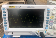
However, I’ve also had a funky waveform all the time, before and after replacing the cap.
Any ideas? Or is this what they mean when the say portable generators are “dirty”.
it’s a model 0G9811 GP7000E brushless.

thanks!
 

Attachments

  • BD8AB095-8068-4EFA-B295-5673C020D1A6.jpeg
    BD8AB095-8068-4EFA-B295-5673C020D1A6.jpeg
    232.5 KB · Views: 40
To avoid these ads, REGISTER NOW!

rlitman

Well-known member
Joined
Oct 18, 2010
Messages
24,773
Location
Long Island
What was the waveform like before you changed the cap? What's the waveform without load, and with a resistive load?

edit: I looked up the manual for your scope, and it appears that it is capable of giving an FFT spectrum graph. That will be MUCH more useful than a picture of a sinewave. And yes, that is "dirty" power.
 
Last edited:

nadogail

Well-known member
Joined
Jan 23, 2009
Messages
32,322
Location
Coronado, CA
When Generator power is described as "Dirty", generally they are telling you that your generator is not producing a pure sine wave output.
 

FMB4

Well-known member
Joined
Jan 19, 2017
Messages
2,926
Yep, that port gen output is just a bit dirty. Some electronics, such as non battery backup powered desktop PCs, etc might not like it so much. Laptops, and most appliances, should be OK tho.
 

u3b3rg33k

Well-known member
Joined
Dec 18, 2017
Messages
4,078
Is that picture under load? if yes, what kind?

I start testing under resistive load - my 1970s 12kVA looks like this with 3kW of balanced resistive load:
1630437978822.png


what's it look like with a big funky load on it (like HIDs)? I couldn't say.
 
OP
W

Wayne L

New member
Joined
Aug 31, 2021
Messages
3
What was the waveform like before you changed the cap? What's the waveform without load, and with a resistive load?

edit: I looked up the manual for your scope, and it appears that it is capable of giving an FFT spectrum graph. That will be MUCH more useful than a picture of a sinewave. And yes, that is "dirty" power.
My scope is a 19_B series, FFT is capable only in the 19_C series (that figures).
I got this waveform signal with the original 28ufd VR, and with the new 38ufd VR.
The old VR kept the output to 108vac max, the new got me up to 124vac.
I took the readings from one leg of the 240 (120 outlet plug), across 120 and common.
The load was (2) blow dryers 1875w each (~30A)
I get the same valleys with no load (of course the v/hz is about 125v/62hz)

since I can’t get an FFT trace, I’ll see what I get when I put a blow dryer on each leg and scope both legs simultaneously (A & B channel)

any other suggestions / ideas?
thanks for the input
 

rlitman

Well-known member
Joined
Oct 18, 2010
Messages
24,773
Location
Long Island
My scope is a 19_B series, FFT is capable only in the 19_C series (that figures).
I got this waveform signal with the original 28ufd VR, and with the new 38ufd VR.
The old VR kept the output to 108vac max, the new got me up to 124vac.
I took the readings from one leg of the 240 (120 outlet plug), across 120 and common.
The load was (2) blow dryers 1875w each (~30A)
I get the same valleys with no load (of course the v/hz is about 125v/62hz)

since I can’t get an FFT trace, I’ll see what I get when I put a blow dryer on each leg and scope both legs simultaneously (A & B channel)

any other suggestions / ideas?
thanks for the input
Oh well. It was worth asking at least. In any case, to my eyes, your waveform appears to have a very significant second harmonic component. I don't need an FFT to see that much, but I can also see that there is much more to this distortion.

My personal experience with even numbered harmonics is quite small (my experience with harmonics is mainly with 3-phase systems as well, that work a little differently), but from what I've seen, harmonics that appear unexpectedly usually are caused by failed capacitors that are part of a passive filter system. Even numbered harmonics are directly harmful to motor loads (among other things), so I would try to get this sorted out.

Just stabbing in the dark here, but another possible cause could be a broken (or hopefully just disconnected) winding in your alternator. That would explain the unexpected voltage drop too.
 

American Locomotive

Well-known member
Joined
Jan 8, 2017
Messages
11,153
Location
Rhode Island
I would definitely check things carefully. IIRC small brushless generators usually have diodes in the rotor that can sometimes go bad.

But honestly that waveform isn't too bad. I bet its some kind of filter or compensation thing to reduce overall harmonic distortion, but introduces that little jig into the waveform.

IMO, it's not a big deal. No electric motors will care about it, and all modern electronics (phones, desktop PCs, etc...) convert all of the incoming power to DC anyways.

The only things that might care about that power are devices with cheap nasty "capacitive dropper" or "resistive dropper" power supplies. Unfortunately this often includes things like small appliances and furnaces.
 
To avoid these ads, REGISTER NOW!

theoldwizard1

Well-known member
Joined
Feb 22, 2011
Messages
43,614
Location
SE MI
I would definitely check things carefully. IIRC small brushless generators usually have diodes in the rotor that can sometimes go bad.

But honestly that waveform isn't too bad. I bet its some kind of filter or compensation thing to reduce overall harmonic distortion, but introduces that little jig into the waveform.
I still haven't wrapped my brain around brushless generators ! Either there is a big permanent magnet on the rotor or a secondary winding that "cut the magnetic field" of a stationary magnet. Diode on the rotor shaft convert it the DC and a capacitor filter it. At least that is what my brain says.


IMO, it's not a big deal. No electric motors will care about it, and all modern electronics (phones, desktop PCs, etc...) convert all of the incoming power to DC anyways.

The only things that might care about that power are devices with cheap nasty "capacitive dropper" or "resistive dropper" power supplies. Unfortunately this often includes things like small appliances and furnaces.
Most everything now uses a switch mode power supply. Very efficient and now inexpensive.
 
Last edited:

MBfreak

MEMBER EMERITUS
Joined
Dec 10, 2010
Messages
2,301
Location
Linkoping , Sweden
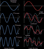
I believe the distorted part of the rising part of each half cycle, and they are mirror images, is caused by a problem in the magnetizing circuit or the AVR system .
I do not think the OPs pic is a second harmonic distorsion.
Here some graphs, among others, a second harmonic 60 Hz with the harmonic being 120 Hz looks like.
Sorry about the crappy pic it is the second row with the red trace the 60/120 Hz waveform
1631727095675.png
 

larry_g

Well-known member
Joined
Apr 28, 2007
Messages
16,931
Location
oregon
I have a Generac GP7000E brushless generator that for the last several years only puts out 108vac at 60hz under load.
On this site I found the answer - replace the 28ufd VR with a 36ufd. That parked me right on top of 124vac @60HZ !!
However, I’ve also had a funky waveform all the time, before and after replacing the cap.
Any ideas? Or is this what they mean when the say portable generators are “dirty”.
it’s a model 0G9811 GP7000E brushless.

thanks!
Your welcome, I'm glad my post earlier worked for you and validated that the larger cap works and is repeatable. Now put the o-scope away and use your generator. They are bottom end machines and what you see is what they do.

lg
no neat sig line
 

MBfreak

MEMBER EMERITUS
Joined
Dec 10, 2010
Messages
2,301
Location
Linkoping , Sweden
TOW states quote Brushless generators do not have AVRs.Unquote
However:
AVR and brushless generators.
Here is a fact on AVR

As the speed of the engine the generator increases, the voltage produced also increases. ... The excitation system monitors the generator output and regulates the magnetic field to maintain the desired voltage. As the load on the generator is increased, an increase in current flow causes the voltage to drop.

Ola
 

theoldwizard1

Well-known member
Joined
Feb 22, 2011
Messages
43,614
Location
SE MI
TOW states quote Brushless generators do not have AVRs.Unquote
However:
AVR and brushless generators.
Here is a fact on AVR

As the speed of the engine the generator increases, the voltage produced also increases. ... The excitation system monitors the generator output and regulates the magnetic field to maintain the desired voltage. As the load on the generator is increased, an increase in current flow causes the voltage to drop.
Nice claim. Do you have any documentation/source to back it up ?

My understanding of the "excitation system" is that it is completely contained inside the rotor. Therefore how does it know the output voltage ?
 

MBfreak

MEMBER EMERITUS
Joined
Dec 10, 2010
Messages
2,301
Location
Linkoping , Sweden
Documentation is all over the internet.
The graphs was taken there, and again, sorry for the crappy pic.
Maybe you can even find a system / block diagram for the unit in question
I think your understanding ( completely contained inside the rotor ) is a bit off the physics governing any rotating electric generating machine.
Here is my take in some detail.
The Excitation system comprises a DC stator field driven by a control system. Typical power < 2 % of main output power,
This field magnetizes a smaller rotor winding which has a rotating set of diodes, the output of which feeds the magnetization of the main generator rotor. Which creates a field by mr Oerstedts old law that creates a voltage in the stator. Frequency depending on number of poles and angular velocity. The active power is all from the combustion engine driving the rotating assembly.
The main generator stator feeds the load and also acts as input to the AVR system.
That`s all from me.

Any further discussion would much improve if a handy websearcher can post a link to the system description of the unit. A complete schematic would be ideal.


Ola
 
Last edited:

larry_g

Well-known member
Joined
Apr 28, 2007
Messages
16,931
Location
oregon
MB, look here for schematic,

That machine is different than mine, if you look at this page of the manual, https://www.manualslib.com/manual/767339/Generac-Power-Systems-Gp1800.html?page=14#manual mine is the one on the left. Capacitive Discharge. No brushes, no slip rings, no adjustment screw.

The above is from the thread https://www.garagejournal.com/forum/threads/generac-gp7000e-voltage-regulator-modify.477507/ Where I did some work on my generator. There are a couple of other links to the manual in the thread if you want to pursue it.

lg
no neat sig line
 

MBfreak

MEMBER EMERITUS
Joined
Dec 10, 2010
Messages
2,301
Location
Linkoping , Sweden
Thanks Larry. That was very enlightening to me.

Now I understand the GENERAC system, both A and B

Type A on page 14 appears to me to be a bit Monte Carlo. Actually never even heard about that kind of solution.
The strange dip in the OPs pic on the rising flange on both pos and neg halfcycle are definitely caused by insufficient excitation energy.

The system B is the standard solution and always works well.

With respect to another sideline above , though quite interesting, FFT analysis will only give relevant answers if the harmonic(s) are exaxt multiples of the base frequency.
If not , it is Fourier maths that will give correct answers
 

rlitman

Well-known member
Joined
Oct 18, 2010
Messages
24,773
Location
Long Island
...With respect to another sideline above , though quite interesting, FFT analysis will only give relevant answers if the harmonic(s) are exaxt multiples of the base frequency.
If not , it is Fourier maths that will give correct answers
True, but harmonics that are not multiples of the base are noise, so they will not have a standing waveform pattern.
 

theoldwizard1

Well-known member
Joined
Feb 22, 2011
Messages
43,614
Location
SE MI
[/QUOTE]
Maybe you can even find a system / block diagram for the unit in question
I think your understanding ( completely contained inside the rotor ) is a bit off the physics governing any rotating electric generating machine.
Here is my take in some detail.
The Excitation system comprises a DC stator field driven by a control system. Typical power < 2 % of main output power,
This field magnetizes a smaller rotor winding which has a rotating set of diodes, the output of which feeds the magnetization of the main generator rotor.
So where does this DC stator field come from before the generator is making power ?
 
To avoid these ads, REGISTER NOW!
Top Bottom