
dwall174
Well-known member
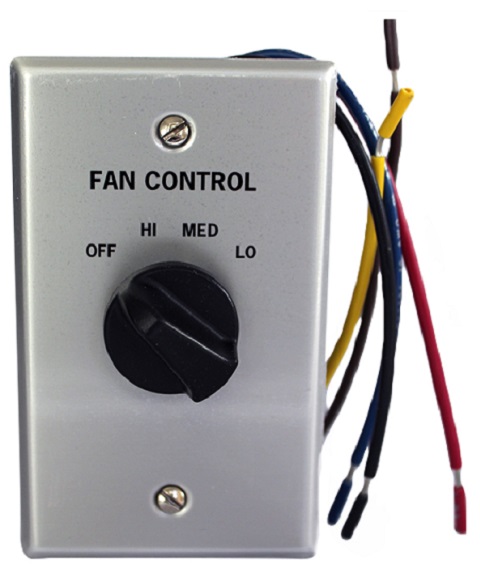
Not really a heating or ac related question, But I'm looking for some basic wiring information on a furnace blower motor.
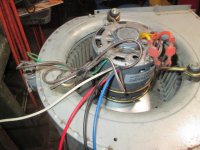
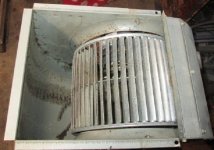
A friend of mine gave me a nice running blower unit from his old furnace, The motor was just replaced about two years ago. Unfourntaly he just found out this year that his heat exchanger was now bad, So he needed to replace the furnace.
I'm planning to use this blower unit to build a ambient style air cleaner for the fine wood dust in my garage.
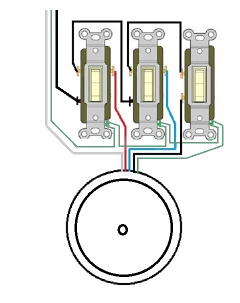
I've seen several DIY designs on the web where the people building the air cleaners just use 3 wall switches to control the speeds! However none of them show the actual wiring for this style set-up?
At about 11:40 minutes into this Video
the builder shows turning on one the switch at a time to control the three speeds.
Does anyone have an idea of what type switches he's using (3-way?) & how he possibly wired this up?
Doug
A friend of mine gave me a nice running blower unit from his old furnace, The motor was just replaced about two years ago. Unfourntaly he just found out this year that his heat exchanger was now bad, So he needed to replace the furnace.
I'm planning to use this blower unit to build a ambient style air cleaner for the fine wood dust in my garage.
I've seen several DIY designs on the web where the people building the air cleaners just use 3 wall switches to control the speeds! However none of them show the actual wiring for this style set-up?
At about 11:40 minutes into this Video
the builder shows turning on one the switch at a time to control the three speeds.
Does anyone have an idea of what type switches he's using (3-way?) & how he possibly wired this up?
Doug


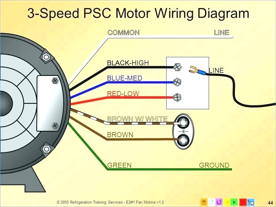

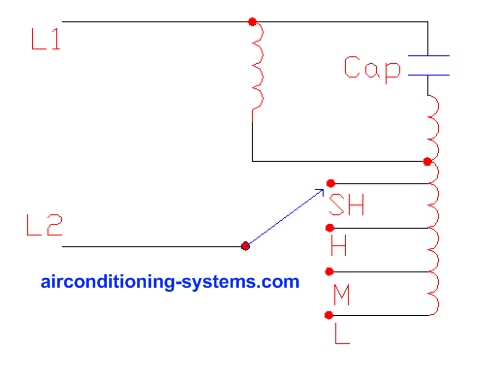
") , You'll just have to know how those fan winding works and bob is your...
, You'll just have to know how those fan winding works and bob is your...