To avoid these ads, REGISTER NOW!

Garage Lighting Plan Help!

Racerhoze

Member
Joined
Oct 1, 2013
Messages
5
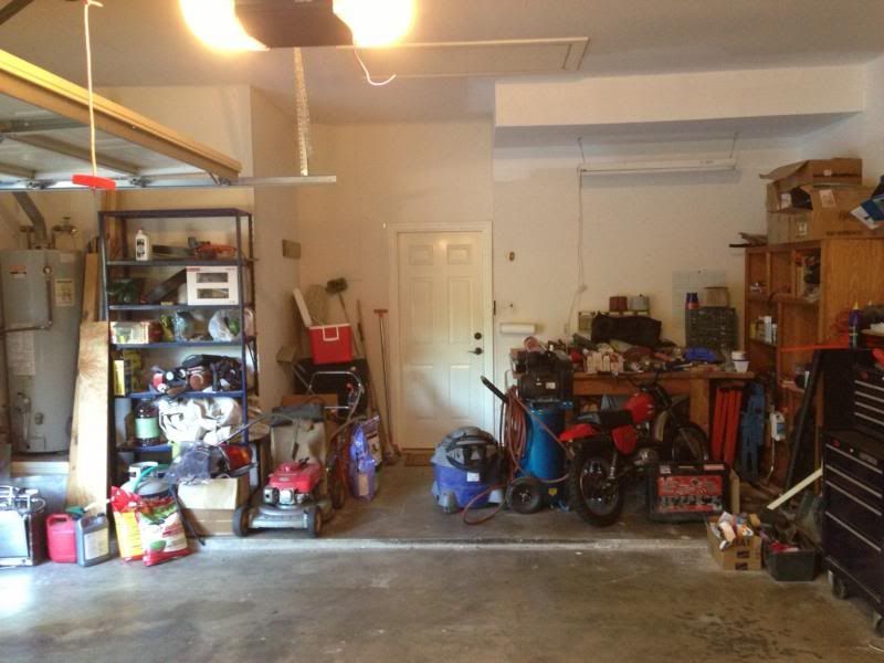
So I recently moved in to a house with the typical one light bulb for the garage. I do a decent amount of automotive work in the garage among other things and it is getting quite annoying not having enough light. The garage light and garage opener outlet are on a 15 amp circuit with two other interior lights. The lights on the circuit including the two bulbs on the opener total up to 530w. The opener says it is a 6a, so I calculated I would be able to run 14 32w fluorescent bulbs safely. My plan was to have two 8ft fixtures, two 4ft fixtures and two single bulb fixtures. The two fixtures parallel to the back wall will be the single bulb 4 foot fixtures. Below are some pictures of my garage, how the existing light is wired, and my plan for light placement. Let me know what you think! (excuse all the junk, the garage will be getting a mega cleanout soon)


To avoid these ads, REGISTER NOW!

pattenp

Well-known member
Joined
Jun 4, 2008
Messages
10,175
Location
Virginia - USA
Too much on a 15A circuit. Based on your numbers that's about 14A. A 15A circuit shouldn't be loaded more than 12A. Put the opener on its own circuit.
 
OP
R

Racerhoze

Member
Joined
Oct 1, 2013
Messages
5
Too much on a 15A circuit. Based on your numbers that's about 14A. A 15A circuit shouldn't be loaded more than 12A. Put the opener on its own circuit.

So how many fluorescent lights would you comfortably add to the circuit? Unfortunately the breaker box is on the complete opposite side of the house, and it would be a somewhat difficult run with the house layout. Though if I can only add one or two lights properly, than I will certainly do it.
 

2ManyProjects

Well-known member
Joined
Jul 18, 2013
Messages
757
So I recently moved in to a house with the typical one light bulb for the garage. I do a decent amount of automotive work in the garage among other things and it is getting quite annoying not having enough light. The garage light and garage opener outlet are on a 15 amp circuit with two other interior lights. The lights on the circuit including the two bulbs on the opener total up to 530w. The opener says it is a 6a, so I calculated I would be able to run 14 32w fluorescent bulbs safely.

As "pattenp" mentioned, that's too much for one light-duty (15A) circuit. You need to consider not only the nominal wattage rating of the tubes themselves, but also the power consumed by the ballasts. This can vary significantly from model to model; but typically, the total load for a twin-tube F32T8 fixture is about 0.55-0.6A. For planning purposes, the latter figure is a reasonable place to throw a dart. Also, fixed load (i.e., "hardwired") circuits should not be loaded beyond 80% of the nominal breaker rating. So for your purposes, that "15A" circuit is really a "12A" circuit. And finally, you would need to make sure that "6A" figure for the door opener really is it's MAXIMUM draw, including the start-up surge (sometimes called "LRA", or "Locked Rotor Amps"), before further loading that circuit.

My plan was to have two 8ft fixtures, two 4ft fixtures and two single bulb fixtures. The two fixtures parallel to the back wall will be the single bulb 4 foot fixtures. Below are some pictures of my garage, how the existing light is wired, and my plan for light placement. Let me know what you think! (excuse all the junk, the garage will be getting a mega cleanout soon)

I'm having a little difficulty understanding your drawing, particularly all those numbers scattered about. Are those dimensions? In what units (inches would sort'a make sense, but it's far from clear)?

However, if, between the drawing and the photos, I've noodled out your garage's general layout correctly, your workbench is located along the back wall, offset somewhat to the right-hand side (as viewed from the driveway). If that is the case, this is the LAST place you want to scrimp on the lighting (such as by dropping back to single-tube fixtures), unless you have some other truly effective task lighting in that area, not shown in the pictures (or mentioned in your description). OTOH, that offset area to the left-rear (again, as viewed from the driveway) looks to be a near-ideal "out of the way" place to put a modestly sized workbench. And indeed it looks like you already have one of those plug-in "shop light" fixtures hanging there. So maybe I'm mis-interpreting that second photo?

The basic locations you've chosen for the new lights aren't terrible; but you might want to tweak them a bit to more closely corespond to the actual vehicle locations. The idea is to put most of the light all AROUND the vehicle, rather than directly overhead or way off to the side, so as to most effectively illuminate the areas you'll actually be working in.

I would also suggest sticking with 4-foot fixtures throughout, for several reasons that I've already belabored several times in recent posts.

So how many fluorescent lights would you comfortably add to the circuit? Unfortunately the breaker box is on the complete opposite side of the house, and it would be a somewhat difficult run with the house layout. Though if I can only add one or two lights properly, than I will certainly do it.

Running at least one new circuit to the garage would be strongly preferable. Make that at least two (ideally three) new circuits, if you use more than trivial power tools, with the non-lighting circuit(s) being fed from 20A breaker(s) using generously-sized wiring (to avoid excessive voltage drop over that implied long run to the service panel). These additional circuits would then feed an array of duplex outlets at various convenient locations around the shop.

However, if that is REALLY not feasible, then the first thing you need to do is confirm the true maximum draw of that garage door opener. Then do the math from there: Deduct the GDO draw from your 12A maximum draw target, then divide the result by approximately 0.3A per F32T8 tube (including any "task lighting" or similar). That won't be precisely accurate; but it will be close enough to get you into the ballpark. And I would strongly suggest that you DON'T try to run smack up against that 12A limit, or you'll leave yourself with insufficient capacity to run a plug in power tool. Figure perhaps 9-10A max, if you want to leave yourself "room" for a vacuum cleaner, electric drill, sander, whatever.


pattenp

Well-known member
Joined
Jun 4, 2008
Messages
10,175
Location
Virginia - USA
I reread your post and let me make sure of what you are saying about the existing load on the circuit. You stated 530 watts of lights. I assume that is existing lighting wattage on the circuit? Is any of that lighting being replaced by the new fluorescent? This how I came up with about 14A load. 530W = 4.42A, 14 X .25A = 3.5A, so 4.42+3.5+6=13.92A. Based on your existing load you shouldn't add more than three 2 lamp F32T8 fixtures.

So how many fluorescent lights would you comfortably add to the circuit? Unfortunately the breaker box is on the complete opposite side of the house, and it would be a somewhat difficult run with the house layout. Though if I can only add one or two lights properly, than I will certainly do it.
 
OP
R

Racerhoze

Member
Joined
Oct 1, 2013
Messages
5
Thank you guys for all the responses, I really appreciate it!

Now to answer some questions:

The existing circuit for the garage door opener and light contains the following:
-Garage door motor & 2x100 watt bulbs
-100 watt bulb fixture (going to be replaced)
-laundry room light fixture (3x50 watt bulbs)
-light in hallway (3x60 watt bulbs)

The two outlets in the garage are protected by one GFCI, this GFCI circuit has a total of 6 outlets. (two upstairs adjacent to sinks, and two outdoor outlets)

I apologize for the quality of the drawing, all dimensions are in inches. The 195" at the bottom is the garage door opening. I generally tried to place the lights around where the cars would be parked so I would not waste any light on the roof of the cars. I was more hesitant to put lights on the far side of the attic access because that is where the 2nd story of the house is and the attic ends there. I attached a picture to help give a better understanding.

My plan of attack now is to run a new 15a circuit to the garage to power the garage door motor. I will also install another GFCI outlet on the wall with the window off of this new circuit. This should leave plenty of power on the existing lighting circuit to run new fluorescent fixtures. The existing 14/3 running up to the light will then allow two lighting circuits (like many on this board suggest) so that any use of the garage will not require powering up ALL the lights.

2ManyProjects/pattenp,

Where would YOU place 4 foot fixtures in a garage such as mine? There is an existing work bench in the corner (buried in ****).

 
Last edited:

pattenp

Well-known member
Joined
Jun 4, 2008
Messages
10,175
Location
Virginia - USA
I suggest the new circuit to be 20A. The new outlet in the ceiling needs to be GFCI protected. Put the GFCI outlet in the wall then feed the ceiling outlet from it. You can not have the physical GFCI outlet on the ceiling. At some point you may decide to hang a cord reel from the ceiling and will need the extra amps. Even if you don't do a cord reel, 20A outlet circuits are best.
 
To avoid these ads, REGISTER NOW!
OP
R

Racerhoze

Member
Joined
Oct 1, 2013
Messages
5
I suggest the new circuit to be 20A. The new outlet in the ceiling needs to be GFCI protected. Put the GFCI outlet in the wall then feed the ceiling outlet from it. You can not have the physical GFCI outlet on the ceiling. At some point you may decide to hang a cord reel from the ceiling and will need the extra amps. Even if you don't do a cord reel, 20A outlet circuits are best.

I thought the ceiling outlet would not need to be GFCI protected, and you think 15A would not be adequate for 2 outlets? The largest current draw is the compressor (seen in one of my earlier pictures)
 

pattenp

Well-known member
Joined
Jun 4, 2008
Messages
10,175
Location
Virginia - USA
All outlets in the garage need to be GFCI protected, even ones on the ceiling. This is a NEC requirement. The 15A is just that, adequate. One thing to consider is the door opener is considered fixed in place utilization equipment and it is not to exceed 50% of the circuit amperage, so you are close. What is the amp draw of the compressor? Is it more than 6A? Remember the circuit should be sized to 125% of anticipated load. On a 15A circuit that gives you 12A of working load.
 
Last edited:

2ManyProjects

Well-known member
Joined
Jul 18, 2013
Messages
757
Thank you guys for all the responses, I really appreciate it!

Now to answer some questions:

The existing circuit for the garage door opener and light contains the following:
-Garage door motor & 2x100 watt bulbs
-100 watt bulb fixture (going to be replaced)
-laundry room light fixture (3x50 watt bulbs)
-light in hallway (3x60 watt bulbs)

The two outlets in the garage are protected by one GFCI, this GFCI circuit has a total of 6 outlets. (two upstairs adjacent to sinks, and two outdoor outlets)

OK, in broad strokes...

First, if at all possible, I would want to completely "divorce" the garage loads from the loads inside the house. This is particularly so if that GFCI outlet circuit you mentioned is also feeding stuff in the kitchen. That tends to be a high-load application (toasters, blenders, countertop microwaves, etc.); and so you really don't want any more "stuff" on those circuits than you have to have.

While the existing "bare bulb in the middle of the ceiling" load could be shared with some other light-duty lighting load inside the house, I would NOT want to tack still more lighting onto that circuit, So in effect this becomes irrelevant.

If you MUST share a circuit between the garage door opener and something else, that "something else" probably ought to be one of your (to be installed) 20A outlet circuits. The odds on running the door opener at the same time you're running some sort of power tool are a lot slimmer than the odds on your running the door opener at the same time you've got a lot of lights on. Still, a dedicated circuit for the GDO is best; and if you go that way, 15A is "enough", as long as you don't have much/anything else on that circuit.

I apologize for the quality of the drawing, all dimensions are in inches. The 195" at the bottom is the garage door opening. I generally tried to place the lights around where the cars would be parked so I would not waste any light on the roof of the cars.

And that is a fine basic approach. Good on you for thinking in those terms. I only suggested "tweaking" the locations slightly to make the light distribution as optimized as possible; but the general locations you're already showing are not exactly "bad", at least in terms of lighting up the cars.

I was more hesitant to put lights on the far side of the attic access because that is where the 2nd story of the house is and the attic ends there. I attached a picture to help give a better understanding.

I'm not sure that worked (re: my understanding, anyway :rolleyes2); but I think I get the underlying point. If moving some of those lights 1-2 feet will make installation immensely more difficult, then I'd almost certainly forego that last little bit of perfection, and make do with whatever is reasonably easy to accomplish; call it "close enough", and move on to other parts of the project.

My plan of attack now is to run a new 15a circuit to the garage to power the garage door motor. I will also install another GFCI outlet on the wall with the window off of this new circuit. This should leave plenty of power on the existing lighting circuit to run new fluorescent fixtures.

If you're going to pull new circuits from the breaker panel (which I really think you DO need to do), then do it right, and pull AT LEAST two (maybe three) new circuits. It won't be all that much more work than pulling one, as you'll need to get access to all the same places along the route anyway. The new lighting circuit can be fed from a 15A breaker; but the circuit(s) for your outlets should be on 20A breaker(s). And in all cases, do consider the run length vs. voltage drop, before deciding on what AWG wire to use (more on that later, if need be).

The existing 14/3 running up to the light will then allow two lighting circuits (like many on this board suggest) so that any use of the garage will not require powering up ALL the lights.

I may have missed this; but why do (you think) you have 14/3 going to that light bulb? Normally, that would be 14/2.

2ManyProjects/pattenp,

Where would YOU place 4 foot fixtures in a garage such as mine? There is an existing work bench in the corner (buried in ****).

If, by "in the corner", you are referring to that offset area to the left-rear (as viewed from the driveway) I mentioned previously, then I agree that this seems to be the best place in that garage for a decent workbench, as it is sufficiently out of the way as to not block access to the vehicles, or make fitting them in a "tight" proposition if any of those vehicles are in the "extra large" class.

You'll want some "extra" lighting in that workbench area; but exactly how this should be implemented will depend on the configuration of your bench, and the area immediately around it. There also appears to be a large toolbox adjacent to the bench. You'll also want that to be well-lit, to easily see whatever your searching for in the drawers. The soffit in that area will make installing lights on (or even hanging from) the ceiling a bit problematic. Otherwise, I might suggest three twin-F32T8 fixtures in something of an "L" shape.

Also, based on the first photo you posted, it looks like just a stand-alone bench, with no cabinetry or other forms of on-wall storage. But how likely is that to change in the foreseeable future? If you do put in upper cabinets or similar, some LED-based "countertop" lighting strips mounted on the underside of those cabinets can serve nicely as the task lighting, while imposing very little current draw. And this in turn will mean you'll need less ceiling-mounted lights in that area (just one twin-tube fixture might do it).

I thought the ceiling outlet would not need to be GFCI protected,

Unfortunately, one of the sillier aspects of the latest NEC is that even that ceiling-mounted outlet MUST be GFCI-protected, unless it is grandfathered in as "existing equipment".

and you think 15A would not be adequate for 2 outlets?

Well first, I guarantee you that you WILL want more than two outlets in that garage, before you're done with it. Typical recommendations are for a double-gang box every 4-8 feet all the way around the perimeter, with the bottom of each box at least 49-50 inches off the floor (for reasons which will become obvious the first time you try to store a sheet of plywood or drywall in there). Each of those double-gang boxes would in turn house two duplex outlets (four sockets total), ideally running off two different circuit breakers. So as long as you're pulling wire, NOW is the time to make ready for that.

Secondly, ALL outlet circuits in garages should be of at least 20A capacity, on general principles. The incremental cost to do this (vs. 15A) is trivial; and the extra capacity can very easily be needed, especially if you run big tools (or multiple smaller tools at the same time).

The largest current draw is the compressor (seen in one of my earlier pictures)

WHOA, NELLIE !!!

As soon as you use the word "compressor", you change the game. All but the most puny, light-duty, "homeowner special" P.O.C. compressors will either require, or nearly require, their own circuit, and very possibly a 240V circuit at that. At the very least, running even a "small" compressor off the same circuit as you're running lights and other power tools on is a recipe for problems.

 
Last edited:
OP
R

Racerhoze

Member
Joined
Oct 1, 2013
Messages
5
OK, in broad strokes...

First, if at all possible, I would want to completely "divorce" the garage loads from the loads inside the house. This is particularly so if that GFCI outlet circuit you mentioned is also feeding stuff in the kitchen. That tends to be a high-load application (toasters, blenders, countertop microwaves, etc.); and so you really don't want any more "stuff" on those circuits that you have to have.
The GFCI in the Garage is not shared with the kitchen, it has its own GFCI circuit.
While the existing "bare bulb in the middle of the ceiling" load could be shared with some other light-duty lighting load inside the house, I would NOT want to tack still more lighting onto that circuit, So in effect this becomes irrelevant.
If you MUST share a circuit between the garage door opener and something else, that "something else" probably ought to be one of your (to be installed) 20A outlet circuits. The odds on running the door opener at the same time you're running some sort of power tool are a lot slimmer than the odds on your running the door opener at the same time you've got a lot of lights on. Still, a dedicated circuit for the GDO is best; and if you go that way, 15A is "enough", as long as you don't have much/anything else on that circuit.
And that is a fine basic approach. Good on you for thinking in those terms. I only suggested "tweaking" the locations slightly to make the light distribution as optimized as possible; but the general locations you're already showing are not exactly "bad", at least in terms of lighting up the cars.
I'm not sure that worked (re: my understanding, anyway :rolleyes2); but I think I get the underlying point. If moving some of those lights 1-2 feet will make installation immensely more difficult, then I'd almost certainly forego that last little bit of perfection, and make do with whatever is reasonably easy to accomplish; call it "close enough", and move on to other parts of the project.
I am trying to think how I could better explain. The attic above the majority of the garage is open space except for the area between the attic access door and the entry door.
If you're going to pull new circuits from the breaker panel (which I really think you DO need to do), then do it right, and pull AT LEAST two (maybe three) new circuits. It won't be all that much more work than pulling one, as you'll need to get access to all the same places along the route anyway. The new lighting circuit can be fed from a 15A breaker; but the circuit(s) for your outlets should be on 20A breaker(s). And in all cases, do consider the run length vs. voltage drop, before deciding on what AWG wire to use (more on that later, if need be).


I may have missed this; but why do (you think) you have 14/3 going to that light bulb? Normally, that would be 14/2.
I say that because the light is switched and the outlet is constantly hot, therefore there has to be two hot wires up there. Take another look at my picture of how they are wired from the back side.
If, by "in the corner", you are referring to that offset area to the left-rear (as viewed from the driveway) I mentioned previously, then I agree that this seems to be the best place in that garage for a decent workbench, as it is sufficiently out of the way as to not block access to the vehicles, or make fitting them in a "tight" proposition if any of those vehicles are in the "extra large" class.
You'll want some "extra" lighting in that workbench area; but exactly how this should be implemented will depend on the configuration of your bench, and the area immediately around it. There also appears to be a large toolbox adjacent to the bench. You'll also want that to be well-lit, to easily see whatever your searching for in the drawers. The soffit in that area will make installing lights on (or even hanging from) the ceiling a bit problematic. Otherwise, I might suggest three twin-F32T8 fixtures in something of an "L" shape.
The soffit area is actually to accommodate plumbing from the bathroom located directly above. (Part of the reason I say wiring over there will be more difficult.)
Also, based on the first photo you posted, it looks like just a stand-alone bench, with no cabinetry or other forms of on-wall storage. But how likely is that to change in the foreseeable future? If you do put in upper cabinets or similar, some LED-based "countertop" lighting strips mounted on the underside of those cabinets can serve nicely as the task lighting, while imposing very little current draw. And this in turn will mean you'll need less ceiling-mounted lights in that area (just one twin-tube fixture might do it).
Good point, I actually have cabinets I intend to mount on the walls ready to go.
Unfortunately, one of the sillier aspects of the latest NEC is that even that ceiling-mounted outlet MUST be GFCI-protected, unless it is grandfathered in as "existing equipment".
Well first, I guarantee you that you WILL want more than two outlets in that garage, before your done with it. Typical recommendations are for a double-gang box every 4-8 feet all the way around the perimeter, with the bottom of each box at least 49-50 inches off the floor (for reasons which will become obvious the first time you try to store a sheet of plywood or drywall in there). Each of those double-gang boxes would in turn house two duplex outlets (four sockets total), ideally running off two different circuit breakers. So as long as you're pulling wire, NOW is the time to make ready for that.
Secondly, ALL outlet circuits in garages should be of at least 20A capacity, on general principles. The incremental cost to do this (vs. 15A) is trivial; and the extra capacity can very easily be needed, especially if you run big tools (or multiple smaller tools at the same time).
WHOA, NELLIE !!!
As soon as you use the word "compressor", you change the game. All but the most puny, light-duty, "homeowner special" P.O.C. compressors will either require, or nearly require, their own circuit, and very possibly a 240V circuit at that. At the very least, running even a "small" compressor off the same circuit as you're running lights and other power tools on is a recipe for problems.
http://www.northerntool.com/shop/to...i_sku=305173&gclid=CI_vyaK0-7kCFaXm7AodrwEA5w
There is a link to the compressor that I have.
 

pattenp

Well-known member
Joined
Jun 4, 2008
Messages
10,175
Location
Virginia - USA
Your compressor pulls 15 amps @ 120 volts. You should have a 20 amp circuit for it. If you use a 15 amp circuit you should have no other loads in that circuit at all when using the compressor.
 

pattenp

Well-known member
Joined
Jun 4, 2008
Messages
10,175
Location
Virginia - USA
The wire running to the light box is 14/3 as you say because there is a switch loop. You should have a constant hot in the light box that feeds the outlet box..
 
To avoid these ads, REGISTER NOW!
Top Bottom