To avoid these ads, REGISTER NOW!

Give this the hairy eyeball for me

z28snksknr

Well-known member
Joined
Jul 8, 2009
Messages
1,827
Location
Turnersville, NJ
I'm trying to come up with a design to mount my struts to my frame. The top plate was easy enough to figure out, but i wanted to run my (4th) design by you guys for some input. Here's some pics of what I'm trying to mount:

0c417954.jpg


ca8f5617.jpg


f1936187.jpg


I'm going to weld DOM tubing around the perimeter of the top plate to make it stronger- here's my best attempt at representing that with cardboard and tape:

a8ab2560.jpg


I'll add two vertical supports using DOM tubing, attached to an L-shaped plate that will attach to the frame to spread the load out. I may make that plate 2 smaller pieces since the 14" plate is a bit overkill i think:
d4a88415.jpg


And side gussets that will warp around to the front of the top plate (its hard to tell from the pic, but there is only a 3-4" space between where the two gussets meet the top plate - almost all the way around it.
b2fdfd8e.jpg


674fee6d.jpg


So, it is strong enough? Is there a simpler, or more aesthetically pleasing scheme? I'll need to shorten this mount since the actual ride height will compress the struts ~3", but I have no way of doing that, so i'll have to try it, check ride height, and keep cutting until i get the stance i want.

Thanks in advance!!
 
To avoid these ads, REGISTER NOW!
OP
Z

z28snksknr

Well-known member
Joined
Jul 8, 2009
Messages
1,827
Location
Turnersville, NJ
I'm already thinking, looking at that last pic now, that i should extend down both the side gussets to the left hand side of the frame a bit. That way, it's attached to the frame on 3 sides instead of just 2.
 

bad_idea

Well-known member
Joined
Jun 11, 2011
Messages
4,335
Location
Pasquotank, NC
I haven't tackled a project of that nature, yet. I would cruise the scrap yards and see how the OEMs do it.
 

racingtadpole

Well-known member
Joined
Dec 3, 2011
Messages
2,029
Location
The far side of crazy.. but sometimes Australia
My two cents worth..

Turn the angle on top of the chassis rail into an inverted U section.
Extend the gusset that comes from the top plate to the chassis rail down to the bottom of the inverted U section. If you make that a bit less scalloped you can put some lightening holes in such a place to allow you to remove the upper arm bolts.
On the inner side of the chassis rail, extend a gusset up from the bottom of the inverted U to somewhere up the tubing.
Put some lightening holes in the big side gussets, its the triangulation thats adding the strength, so you can take a bit of metal out to make it a bit lighter.

Thats how Id do it based on the cardboard aided design you show, Im sure others will have different opinions.
 

gorilla

Well-known member
Joined
Dec 13, 2007
Messages
1,656
The design and placement of that bracket affects both the ride height and the front end alinement of the truck. It also supports a lot of load both static and dynamic. You may want to tack up the bracket hang the engine in it and do a rough front end alinement before you make anything solid. Do you have any idea what caster-camber values you want when your done? perhaps some front end expert on the board could give you some values to shoot for.
 
OP
Z

z28snksknr

Well-known member
Joined
Jul 8, 2009
Messages
1,827
Location
Turnersville, NJ
My two cents worth..

Turn the angle on top of the chassis rail into an inverted U section.
Extend the gusset that comes from the top plate to the chassis rail down to the bottom of the inverted U section. If you make that a bit less scalloped you can put some lightening holes in such a place to allow you to remove the upper arm bolts.
On the inner side of the chassis rail, extend a gusset up from the bottom of the inverted U to somewhere up the tubing.
Put some lightening holes in the big side gussets, its the triangulation thats adding the strength, so you can take a bit of metal out to make it a bit lighter.

Thats how Id do it based on the cardboard aided design you show, Im sure others will have different opinions.

:bowdown: I understand that approach and will definately incorporate your comments. I have some limitations on how much less I can scallop the sides because of the control arm swing clearance, but I may cut some small holes out. Thanks for the input :beer:

The design and placement of that bracket affects both the ride height and the front end alinement of the truck. It also supports a lot of load both static and dynamic. You may want to tack up the bracket hang the engine in it and do a rough front end alinement before you make anything solid. Do you have any idea what caster-camber values you want when your done? perhaps some front end expert on the board could give you some values to shoot for.

The suspension is from a '02 Tans Am, and I intend to keep the alignment specs identical since I'm no suspension designer. I agree with your thoughts on tacking in the brackets and then putting the load on the front end to check it. The camber will definately change with a 2" spring compression. The expected weight on the front axle is ~1700 lbs, so I'm guessing my tacks will need to be strong and plentiful.

I'll try to post an update after the holiday weekend. Thank you guys for your input - I've learned a while ago that this site is a phenomenal resource for intelligent and meaningful input. Thanks again!
:rocker:
 

Agent1320

Well-known member
Joined
Aug 5, 2011
Messages
398
Location
Texas
I got the scary eyeball now after looking at this.

If you're gung-ho about using this 4th gen stuff for whatever reason, you need to think outside of just flat plate steel and gussets. Something along the lines of a tubular support system with ERW or DOM tubing running from the front of the frame rail towards the firewall and down again to the frame rail. Then setting the top mount of the strut into the bottom of this tubing structure and possibly even a bolt in strut tower brace to keep things from flexing inward.

Look at the geometry of the suspension design...imagine the forces working here and how they'll affect the setup you're mocking right now. It's going to be a hell of alot of work to be safe and function how you want it to.

You're going to go through alot of work just to get IFS on that truck frame. Easiest and cheapest thing is to swap a 2nd Gen F-Body subframe under the framerails. The truck frame sits on top of the F-Body subframe, so it's much safer than just grafting in a later IFS to the stock rails. The 2nd gen stuff is great and there's a ton of aftermarket parts to beef them up to handle like they are on rails. Same for the Volare clip...stock frame is just notched along the bottom to the contour of the Volare subframe and then welded to it. You have adjustable ride height with the torsion bars on the Volare clip and there's aftermarket drop spindles, brake kits, and bushing kits for them.\

I had a '56 F100 with a '78 Camaro clip under it. Stock brakes, power steering, and a big Addco sway bar and it was the right heigh, it handled great, and rode like a factory Camaro. I could have easily upgraded to tubular control arms for more adjustability and weight savings, upgraded the brakes if I wanted to, installed fancy bushings to tighten it up, and could easily have installed air bags, coilovers, lowering springs, or progressive springs to tune the front end. But it was a daily driver and the stock F-body stuff was aces compared to the factory truck I-beam suspension in terms of driveability and handling.
 

larry_g

Well-known member
Joined
Apr 28, 2007
Messages
16,899
Location
oregon
I think I would take a clue from the old Mustangs where they tied the top of the towers together with a brace from cowl and each other. A lot of dynamic forces in action there from braking and turning.

as Agent 1320 said
Something along the lines of a tubular support system with ERW or DOM tubing running from the front of the frame rail towards the firewall and down again to the frame rail. Then setting the top mount of the strut into the bottom of this tubing structure and possibly even a bolt in strut tower brace to keep things from flexing inward.

lg
no neat sig line
 
OP
Z

z28snksknr

Well-known member
Joined
Jul 8, 2009
Messages
1,827
Location
Turnersville, NJ
I got the scary eyeball now after looking at this.

Look at the geometry of the suspension design...imagine the forces working here and how they'll affect the setup you're mocking right now. It's going to be a hell of alot of work to be safe and function how you want it to.

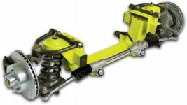
Thank you for your feedback. I have some questions though regarding how the forces of this system differ in magnitude from an aftermarket IFS that uses coilovers and weld-on brackets like the one in the attached pic. The vertical forces are the same, only I'm increasing the height of the top mount above the frame by 2-3". I realize there is some leverage as a result, but that's why I'm adding DOM tubing and (per the above poster) adding gussets to a 3-sided frame plate. That's a whole lot more strength than the mount in the aftermarket kits. I don't quite agree that this scheme is faulty and unsafe, if built correctly.

I was tossing around the idea of using a tower brace spanning the engine compartment. I may still add that after the engine is installed, but was hoping to have a robust enough mounting system that it wouldn't be an issue.
 

Attachments

  • ifs.jpg
    ifs.jpg
    12.2 KB · Views: 50

bad_idea

Well-known member
Joined
Jun 11, 2011
Messages
4,335
Location
Pasquotank, NC
The main point I gathered from Agent1320 is the ease of install. Having owned a second gen with an upgraded suspension and owning a 2002 z28 now, I can say the 2nd gen susp is a solid choice as far as handling goes. You should be able to pick up a 2nd gen front sub frame for cheap. I also agree with you that the 4th gen stuff should work just fine, as long as your a good welder and the attachment points are well engineered.
 

gorilla

Well-known member
Joined
Dec 13, 2007
Messages
1,656
The weld in front end uses gussets from the crossmember up to the frame to stiffen it up.Do you have room to do this? I think that what you're doing will be strong enough I'd worry more about getting the alinement right.
 
To avoid these ads, REGISTER NOW!

EdT

Well-known member
Joined
Sep 21, 2010
Messages
1,104
Location
North Georgia
My "gut" reaction when looking at the pics is that you need something to tie the tops of the strut towers together. I doubt that the frame was designed with a lot of torsional stiffness and even if you gusset and brace the hell out of the tower-to-frame joint every time the suspension tries to move up, it's going to twist the frame and , eventually, something bad may happen. A mustang like brace as suggested above might help, but something straight across would be even better as long as the engine isn't in the way which it probably is. This probably isn't the first time this transplant has been done, so it would be really worth some time to see what's already ben done. Good luck with it.
 

Agent1320

Well-known member
Joined
Aug 5, 2011
Messages
398
Location
Texas
The Mustang II style kit you show in the photo above does have the same basic geometry, but as you also noted...your 4th gen has more leverage working against it. It's like trying to turn a nut with your hand on a socket...or using a ratchet to turn the socket... Just a little more leverage increases the working forces substantially. So the reason this design works with the stock Mustang II, and the aftermarket MII kits is because of how short the springs are, which locates the top hats close to the frame rail, ie: not as much leverage, but you already know that.

There's no doubt that you could make it work and be safe and reliable and handle properly, but the amount of work to do so will be double or triple over a 2nd gen subframe conversion. Plus, after all the tubing and gussets and what not, you might not have much room for inner fender wells.

If you're wanting to use this 4th gen because you already have it and it's cheap, I understand that. Just keep in mind you could save yourself alot of headaches and extra work/engineering/time if you were to go back to the drawing board and use another setup. You could easily sell the 4th gen parts and have enough scratch to buy a complete 2nd gen clip.

If you're wanting to use this clip because you want to be different, or because you really really really want a 4th gen IFS equipped classic...then by all means get after it. Just make sure you do careful planning and engineering and precision welding. Another thing to look into is using a different strut all together...something shorter. The upper and lower control arms don't really car how far apart they are from eachother, as long as the geometry between them remains the same. Doing this will drop the top of the strut mount lower and closer to the frame which results is less headache.
 
Last edited:
OP
Z

z28snksknr

Well-known member
Joined
Jul 8, 2009
Messages
1,827
Location
Turnersville, NJ
The Mustang II style kit you show in the photo above does have the same basic geometry, but as you also noted...your 4th gen has more leverage working against it. It's like trying to turn a nut with your hand on a socket...or using a ratchet to turn the socket... Just a little more leverage increases the working forces substantially. So the reason this design works with the stock Mustang II, and the aftermarket MII kits is because of how short the springs are, which locates the top hats close to the frame rail, ie: not as much leverage, but you already know that.

There's no doubt that you could make it work and be safe and reliable and handle properly, but the amount of work to do so will be double or triple over a 2nd gen subframe conversion. Plus, after all the tubing and gussets and what not, you might not have much room for inner fender wells.

If you're wanting to use this 4th gen because you already have it and it's cheap, I understand that. Just keep in mind you could save yourself alot of headaches and extra work/engineering/time if you were to go back to the drawing board and use another setup. You could easily sell the 4th gen parts and have enough scratch to buy a complete 2nd gen clip.

If you're wanting to use this clip because you want to be different, or because you really really really want a 4th gen IFS equipped classic...then by all means get after it. Just make sure you do careful planning and engineering and precision welding. Another thing to look into is using a different strut all together...something shorter. The upper and lower control arms don't really car how far apart they are from eachother, as long as the geometry between them remains the same. Doing this will drop the top of the strut mount lower and closer to the frame which results is less headache.

Again, thanks for your input. I think with the gussets, a C channel plate to the frame, making the frame mount wider to spread the torsional load on the frame out, and adding a strut tower brace should be enough belts and suspenders to get the job done. I'm comitted to the 4th gen k-member, and I'm enjoying the challenge of getting it to work because in the end I'll have a modern suspension, steering, and braking system that has cheap parts support and room to upgrade as the budget permits. I'm also very familiar with the setup. Adding ABS to the truck later on would be a breeze since the hardware is already there and that's something that no aftermarket kit or 2nd gen subframe could do.

I'll try to get to it this weekend and post my improvements for one final check.
 

Brad54

Well-known member
Joined
Jun 13, 2006
Messages
4,646
I like those brackets better than the OP's.

To the OP: think about this: all the forces of the truck are being held by the top mount of that strut. If you really think about it, it's that top mount that is anchoring the spring, which is supporting all the weight... and the forces as the suspension goes through its travel.

If you just tie in to the top plane of that frame rail, you're transmitting all those forces to the frame rail... something in that area will flex, get weak, fatigue and break--either the welds, the top of the frame, or your bracket.

You need to come down on both sides of the frame rail and tie it all together. And if you can figure out a way to tie it in to the cross member, that'd be even better.

-Brad
 
OP
Z

z28snksknr

Well-known member
Joined
Jul 8, 2009
Messages
1,827
Location
Turnersville, NJ
Once I get the engine in place, I'll try to find a spot for a crossmember to tie the frame rails together up front.

Just to ground myself in the "it's not strong enough" area a bit, I noticed that the factory front suspension on this truck was connected by two small L-shaped brackets (smaller than my hand) on the bottom of the frame for each side using 4 rivets each to mount the leaf springs to. I'm easily exceeding the strength of that system here, and probably shaving some weight in the process.
 

cyamaha2007

Well-known member
Joined
Apr 20, 2009
Messages
2,001
Location
St.Charles MO
I think it looks great i did this on buddies ranger with a ls swap. He bought a donor car for the ls and t56. We just had the wild idea to try it out. It turned out pretty good. What i did was measure my car 01 ta and remake that setup on the ford frame. I did a write up on ls1 tech i think under conversions. And remember that generally what feels right is right. I think that jumping into a project and doing what it takes is one reason this country is so great.
 
OP
Z

z28snksknr

Well-known member
Joined
Jul 8, 2009
Messages
1,827
Location
Turnersville, NJ
I think it looks great i did this on buddies ranger with a ls swap. He bought a donor car for the ls and t56. We just had the wild idea to try it out. It turned out pretty good. What i did was measure my car 01 ta and remake that setup on the ford frame. I did a write up on ls1 tech i think under conversions. And remember that generally what feels right is right. I think that jumping into a project and doing what it takes is one reason this country is so great.

Thanks! I'll have to go find that thread and take a look!! :beer: Glad I'm not the only one that has ever done this.
 
To avoid these ads, REGISTER NOW!
Top Bottom