Tools Required
J 36850 Assembly Lubricant (or equivalent)
Object Number: 768830
Click here for detailed picture of above image.
1. Inspect the control valve body spacer plate and gasket assembly (396) for the following conditions:
• Plugged holes
• Damaged gasket sealing surfaces
• Plugged or damaged screen/seal assemblies (382)
Object Number: 12988
Click here for detailed picture of above image.
1. Inspect each ball check valve seat (one at a time) on the spacer plate (370) for excessive peening.
• Place a ball check valve (372) on each seat
• Use a flashlight to look for visible light between the ball check valve and the seat.
• If light is visible between the ball check valve and the seat, replace the spacer plate assembly (370).
Object Number: 48229
Click here for detailed picture of above image.
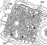
1. Install 4 ball check valves (372) into the case cover (400), in the positions shown. Use J 36850 or equivalent in order to hold the ball check valves in the case cover (400).
Object Number: 49399
Click here for detailed picture of above image.
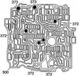
1. Install the 2 larger ball check valves (373) and the 4 smaller ball check valves (372) into the control valve body (300). Use J 36850 or equivalent in order to retain the ball check valves in the control valve body (300).
Object Number: 768831
Click here for detailed picture of above image.
1. Install the screen/seal assemblies (382) into the spacer plate and gasket assembly (396).
2. Install the spacer plate and gasket assembly (396) onto the control valve body (300).
3. Install the bolts (368) to hold the spacer plate and gaskets onto the control valve body (300).
Object Number: 49400
Click here for detailed picture of above image.
1. Install the control valve body alignment sleeve (410) into the case cover (400).
Important:
• Use the control valve body alignment sleeve (410) and turbine shaft sleeve in the case cover (400) as guides.
• Be sure that the ball check valves do not drop out of the control valve body (300) during assembly.
2. Install the control valve body (300) onto the case cover (400).
Object Number: 840847
Click here for detailed picture of above image.
1. Install the transmission fluid pressure (TFP) manual valve position switch assembly (395) onto the control valve body (300).
Object Number: 840845
Click here for detailed picture of above image.
Important: Finger start the bolts to prevent cross-threading.
1. Install the control valve body bolts (374–381, 384) as indicated.
Important:
• Tighten the bolts in a spiral pattern starting with the bolts at the center of the control valve body.
• If the bolts are tightened at random, valve bores may become distorted and inhibit proper valve operation.
Notice: Refer to Fastener Notice in Cautions and Notices.
2. Tighten the control valve body bolts (374–381, 384).
Tighten
• 374 — 12 N·m (106 lb in)
• 375 — 12 N·m (106 lb in)
• 376 — 12 N·m (106 lb in)
• 377 — 12 N·m (106 lb in)
• 378 — 12 N·m (106 lb in)
• 379 — 16 N·m (11 lb ft)
• 380 — 25 N·m (18 lb ft)
• 381 — 8 N·m (70 lb in)
• 384 — 12 N·m (106 lb in)