To avoid these ads, REGISTER NOW!

Grinder wiring, is this correct?

The Cobbler

Super Moderator
Staff member
Joined
Oct 24, 2013
Messages
26,204
Location
Niagara Region, Ontario, Canada
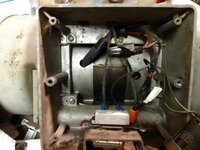
was going to replace the cord on my vintage bench grinder . not sure that it is correctly wired?
the hot goes to the switch, . the neutral ( white taped) lead ties to the capacitor
both hot & neutral come out of the motor with a red & brown tied together .
my mind tells me the cap should be the switched side?
thanks for replying
 

Attachments

  • 305020-e9ea3dd37f6cd6c49c9208e64b26a7aa.jpg
    305020-e9ea3dd37f6cd6c49c9208e64b26a7aa.jpg
    8.7 KB · Views: 47
  • grinder.jpg
    grinder.jpg
    678.1 KB · Views: 45
To avoid these ads, REGISTER NOW!

Zeke

Well-known member
Joined
Aug 13, 2009
Messages
17,176
Location
Long Beach CA, the sewer by the sea.
If it ran, wire it the same as you found it. Understanding the function of a capacitor in a single phase induction motor is difficult. But there is a 2nd winding in there that uses the capacitor the way you found it wired. Helps to turn the motor in the correct direction and get it going.

That's all I understand myself. But I rely on don't fix (change) it if it ain't broke.
 

Zeke

Well-known member
Joined
Aug 13, 2009
Messages
17,176
Location
Long Beach CA, the sewer by the sea.
That was my answer, why do you think it's wrong? Are you thinking of a capacitor as a resistor? This might not be very technically correct, but think of the capacitor as a phase shift of the current before it competes the circuit to neutral/ground. It's just doing what needs to be done using a 2nd winding. It may very well disconnect via a centrifugal switch.
 
To avoid these ads, REGISTER NOW!

TractorJeff

Well-known member
Joined
Dec 8, 2013
Messages
3,309
Location
Elkhorn, WI
The capacitor would theoretically drain down on the Neutral/White wire side. This is probably good?

Its early in the morning, first cup of coffee. So maybe a useless point?
Either way I would wire it the same as I took it apart. Someone smarter than me wired it according to an Engineering Drawing originally.
 

torqueman2002

Well-known member
Joined
Jun 3, 2009
Messages
6,158
Location
SE Michigan
I'm with TJeff ^, capacitor on the neutral/white wire side, not on the hot/black side. This is from my experience of numerous 'rebuilds' of mostly Craftsman grinders.

I am also on my first cup of java, but have searched many diagrams of grinders with start capacitors, most use a relay instead of a centrifugal switch to control the start-up motor windings.

Given the information/pictures above, my recommendations may need to be adjusted when/if better pictures of the label and wiring are available.

I would replace the power cord and wire it as it came apart and add a chassis ground.
I would replace the light switch with a motor rated power switch.

Note: I typically replace the following when the grinder is being 'rebuilt'.
Bearings
Wire wheels/grinding stones

In the spirit of best practice/safety, replace any missing parts, such as:
spark arrestors
tool rests
eye shields
wheel guards
wheel covers

Here is a diagram of a CM grinder with a start-up capacitor and centrifugal start-up switch. Wire colors may differ from your model.
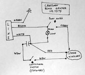
grinder_cm_1157575_01_elec2.jpg

Also, here is a a thread I posted on OWWM website about a CM grinder.
http://vintagemachinery.org/photoindex/detail.aspx?id=12609

Note: The centrifugal switch is fragile and may be damaged when the end bell is removed.
 

nadogail

Well-known member
Joined
Jan 23, 2009
Messages
32,306
Location
Coronado, CA
I am a firm believer in “if it isn’t broken, don’t fix it”.

I don’t pretend to understand everything I think I know. There is no point in arguing with success.
 
To avoid these ads, REGISTER NOW!
Top Bottom