To avoid these ads, REGISTER NOW!

Grounding bar needed?

OneOfEm

Well-known member
Joined
Dec 7, 2015
Messages
255
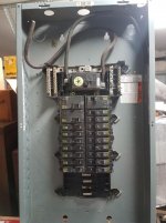
I picked up this panel ($30 for everything, including the breakers shown) to use in the detached workshop that I'm constructing.

attachment.php


From what I've read, I believe that I'll need to add a separate grounding bar: neutrals to neutral bar; grounds to grounding bar. Is that correct? Would it be OK to add one to each side and bond them to each other?

I also will be adding some GFCI breakers, in case someone happens to spot that there are none in the panel...
 

Attachments

  • 2017-08-09 21.47.54.jpg
    2017-08-09 21.47.54.jpg
    139.4 KB · Views: 278
To avoid these ads, REGISTER NOW!

American Locomotive

Well-known member
Joined
Jan 8, 2017
Messages
11,014
Location
Rhode Island
Yup, you will need a separate ground bar. Any big-box store will have the Square D QO ground bar kit in stock.

Make sure your neutral bus is not bonded to the chassis of the panel.
 

pattenp

Well-known member
Joined
Jun 4, 2008
Messages
10,175
Location
Virginia - USA
You do need to add a ground bar. Adding 2 is no problem, they are bonded by being fastened to the case. Be sure to use the Square-D ground bar kit.

GFCI breakers are not required. It will be cheaper to use GFCI receptacles.
 
Last edited:

rlitman

Well-known member
Joined
Oct 18, 2010
Messages
24,662
Location
Long Island
You do need to add a ground bar. Adding 2 is no problem, they are bonded by being fastened to the case. Be sure to use the Square-D ground bar kit...

True, but I'd still bond them with a piece of the same size wire used to bring in the ground to the panel if I had two.

However, one long ground bar should be sufficient.
 

6768rogues

Banned
Joined
Nov 28, 2007
Messages
4,524
Location
Western NY
I have about 10 GFCI receptacles lined up near my panel. The circuits go out from there. Since I have a lot of circuits and they alternate as they go around the building, I only go to one place if one trips and there is never something leaning on the wall in front of one.
 
OP
O

OneOfEm

Well-known member
Joined
Dec 7, 2015
Messages
255
I have about 10 GFCI receptacles lined up near my panel. The circuits go out from there. Since I have a lot of circuits and they alternate as they go around the building, I only go to one place if one trips and there is never something leaning on the wall in front of one.

Doh.

I forgot that only one GFCI receptacle is needed per circuit. I'm sure that would be cheaper.
 

wyliesdiesels

Well-known member
Joined
Aug 14, 2012
Messages
20,073
Location
Modesto, CA
I picked up this panel ($30 for everything, including the breakers shown) to use in the detached workshop that I'm constructing.

From what I've read, I believe that I'll need to add a separate grounding bar: neutrals to neutral bar; grounds to grounding bar. Is that correct? Would it be OK to add one to each side and bond them to each other?

I also will be adding some GFCI breakers, in case someone happens to spot that there are none in the panel...

in addition to the ground bar, you will need 2 ground rods. And make sure your feeder is 4 wire.

How long is the wire run?

What are your loads?

The bus stab (2nd from bottom, on the "A" leg) is burnt, so you won't be able to use those particular circuits. :sad:

On that note i would remove all the branch breakers and check the stabs for burn marks...

Never know whats lurking beneath on these "garage sale" deals...
 
Last edited:

mm08822

Well-known member
Joined
Jan 13, 2012
Messages
6,051
Location
NJ
The bus stab (2nd from bottom, on the "A" leg) is burnt, so you won't be able to use those particular circuits. :sad:

Zooming in on it appears that an errant wire contacted it vs. a cb connected and left brewing away.

As suggested, I would still pull all cb's and inspect both busbar and cb contact points.
 
To avoid these ads, REGISTER NOW!
OP
O

OneOfEm

Well-known member
Joined
Dec 7, 2015
Messages
255
The run is 280' total with another subpanel that I've already installed at the mid-point. I have a 100 amp breaker at the main panel and am using 4/0-4/0-2/0-4 MHF in conduit. The local supplier was able to do 4/0 for less than 2/0, since it's a stocked size.

I spliced a smaller wire to fit the breaker and lugs (with rubber tape then 33+).

I have two ground rods at the mid-point panel. We poured the slab two weekends ago for the workshop, and I was able to utilize a Ufer ground there.

I will check out the used panel thoroughly before I commit to using it. I'm just looking ahead at the electrical details because I will be doing the cable run this weekend so that I can backfill the trench (inspector asked for 3 pieces of conduit to be placed for measurement ports).
 

mm08822

Well-known member
Joined
Jan 13, 2012
Messages
6,051
Location
NJ
The run is 280' total with another subpanel that I've already installed at the mid-point. I have a 100 amp breaker at the main panel and am using 4/0-4/0-2/0-4 MHF in conduit. The local supplier was able to do 4/0 for less than 2/0, since it's a stocked size.

I spliced a smaller wire to fit the breaker and lugs (with rubber tape then 33+).

I have two ground rods at the mid-point panel. We poured the slab two weekends ago for the workshop, and I was able to utilize a Ufer ground there.

I will check out the used panel thoroughly before I commit to using it. I'm just looking ahead at the electrical details because I will be doing the cable run this weekend so that I can backfill the trench (inspector asked for 3 pieces of conduit to be placed for measurement ports).

The ufer alone should have been enough, but the 2 extra rods wont be an issue.

What are the details of how this mid-point tap was made?
 
OP
O

OneOfEm

Well-known member
Joined
Dec 7, 2015
Messages
255
The ufer alone should have been enough, but the 2 extra rods wont be an issue.

What are the details of how this mid-point tap was made?

It's another (new) outdoor-rated Square D panel (WAY bigger than needed) with a 100amp main breaker. It's under an open-sided structure, and I've got two other circuits fed from that panel to that building (lights and incidental outlets - minimal load on each). I did that part first mostly so that I'd have a closer covered area with power.

So it's like this: main panel -> mid-point panel (with ground rods) -> workshop panel (Ufer). I have 90 amp breakers in both the main panel and the mid-point panel.
 

mm08822

Well-known member
Joined
Jan 13, 2012
Messages
6,051
Location
NJ
It's another (new) outdoor-rated Square D panel (WAY bigger than needed) with a 100amp main breaker. It's under an open-sided structure, and I've got two other circuits fed from that panel to that building (lights and incidental outlets - minimal load on each). I did that part first mostly so that I'd have a closer covered area with power.

So it's like this: main panel -> mid-point panel (with ground rods) -> workshop panel (Ufer). I have 90 amp breakers in both the main panel and the mid-point panel.

My original reply to this was lost. Take 2.

Just clarifying.....
What are the breaker sizes - Above says two different sizes.
The workshop is at the end of the feeder and is not the mid-point structure.

The 4/0 Al is sized correctly for a 100a full load at the end of the line if you ever reach that load level. However, the midpoint panel loading could effect that if it too handles big loads.
What are the expected loads for each location?
Continuous or random loads?
Simultaneous?

Exactly what are the details of how the tap was made at the mid-point of the feeder to the mid-point panel.......What happened to the conduits, underground, pullbox, jbox, waterproof splices, bugs,lugs, etc?
 
OP
O

OneOfEm

Well-known member
Joined
Dec 7, 2015
Messages
255
My original reply to this was lost. Take 2.

Just clarifying.....
What are the breaker sizes - Above says two different sizes.
The workshop is at the end of the feeder and is not the mid-point structure.

The 4/0 Al is sized correctly for a 100a full load at the end of the line if you ever reach that load level. However, the midpoint panel loading could effect that if it too handles big loads.
What are the expected loads for each location?
Continuous or random loads?
Simultaneous?

Exactly what are the details of how the tap was made at the mid-point of the feeder to the mid-point panel.......What happened to the conduits, underground, pullbox, jbox, waterproof splices, bugs,lugs, etc?

The breaker at the main panel that feeds circuit A to the midpoint building is 90 amp. The main panel breaker (disconnect) at the midpoint building is 100 amp. Circuit A is terminated at the lugs/neutral bar/ground bar (not bonded) in this panel. It's in conduit from the main panel to this panel.

Circuit B starts (will start) at a 90 amp breaker in the midpoint panel and terminate at the lugs/neutral bar/ground bar in the panel in the workshop. It will be in a separate conduit run.

I will have two conduits going into the panel at the midpoint. It may not be the best way, but it seemed to be the easiest for me (vs. trying to figure out pullbox, jbox, waterproof splices, bugs,lugs, etc :eyecrazy:).

I know the 4/0 could handle 100 amp, but I'd already purchased the 90 amp breakers and it's not worth an exchange hassle for capacity that I'll likely never use.

The midpoint panel is in a covered picnic/party area. Other than a circular saw and miter saw during the shop construction, it has 4 strings of LED party lights (already installed and on a lighting circuit) and might have a fan or two, all only while in use for entertaining. The only reason I put a panel there was that I didn't want to run a separate circuit or circuits from the house or shop back to this building since I was already going right beside it with the main run to the shop.

-Edit-

The workshop will be just me. Table saws, RAS, bandsaw, drill press, jointer, planer, sanders, etc - likely only one in use at any given time, although if a friend or one of my sons is over, two might be in use. The lighting will be LED. I will eventually have an air compressor. I have a couple welders - one is a 220 30 amp stick, the other is a little Lincoln MIG. I will also have AC, either a traditional split unit or a couple mini splits.
 
Last edited:
OP
O

OneOfEm

Well-known member
Joined
Dec 7, 2015
Messages
255
The 4/0 conductors will most likely be too large to fit in the lugs of a 90 Amp breaker, or even of the 100 Amp panel.

I've already dealt with that in the main panel and midpoint panel with circuit A.

I spliced a smaller wire to fit the breaker and lugs (with rubber tape then 33+).

I used one of these in a larger size, then the tape mentioned above:

5228dfdb-c09e-4ec7-98c9-d8541df79075_1000.jpg


The hardest part was convincing the 4/0 to bend how and where I wanted it to.
 
Last edited:

mm08822

Well-known member
Joined
Jan 13, 2012
Messages
6,051
Location
NJ
The breaker at the main panel that feeds circuit A to the midpoint building is 90 amp. The main panel breaker (disconnect) at the midpoint building is 100 amp. Circuit A is terminated at the lugs/neutral bar/ground bar (not bonded) in this panel. It's in conduit from the main panel to this panel.

Circuit B starts (will start) at a 90 amp breaker in the midpoint panel and terminate at the lugs/neutral bar/ground bar in the panel in the workshop. It will be in a separate conduit run.

I will have two conduits going into the panel at the midpoint. It may not be the best way, but it seemed to be the easiest for me (vs. trying to figure out pullbox, jbox, waterproof splices, bugs,lugs, etc :eyecrazy:).

I know the 4/0 could handle 100 amp, but I'd already purchased the 90 amp breakers and it's not worth an exchange hassle for capacity that I'll likely never use.

The midpoint panel is in a covered picnic/party area. Other than a circular saw and miter saw during the shop construction, it has 4 strings of LED party lights (already installed and on a lighting circuit) and might have a fan or two, all only while in use for entertaining. The only reason I put a panel there was that I didn't want to run a separate circuit or circuits from the house or shop back to this building since I was already going right beside it with the main run to the shop.

-Edit-

The workshop will be just me. Table saws, RAS, bandsaw, drill press, jointer, planer, sanders, etc - likely only one in use at any given time, although if a friend or one of my sons is over, two might be in use. The lighting will be LED. I will eventually have an air compressor. I have a couple welders - one is a 220 30 amp stick, the other is a little Lincoln MIG. I will also have AC, either a traditional split unit or a couple mini splits.

Understood.
More than one way to do it, but you're good. I was concerned previously reading:
"The run is 280' total with another subpanel that I've already installed at the mid-point." and "I spliced a smaller wire to fit the breaker and lugs (with rubber tape then 33+)."

Seemed like you may have been tapping into a 280' long feeder at mid-point and if it was done underground, I was curious of the details. Actually you have 2 - 140' feeders and a sub-panel off a sub-panel! Have fun.:thumbup:
 
OP
O

OneOfEm

Well-known member
Joined
Dec 7, 2015
Messages
255
It's hard to communicate this type of stuff in words only - especially for those of us who are neophytes. :)
 
To avoid these ads, REGISTER NOW!
Top Bottom