To avoid these ads, REGISTER NOW!

Help: Craftsman Block Grinder Resuscitation

Chiz

Active member
Joined
Jun 11, 2017
Messages
29
Location
Ohio
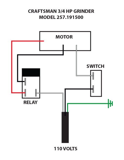
I am new to this site: I need some help trouble shooting this Craftsman Grinder 257.191500.


IMG_0239.jpg


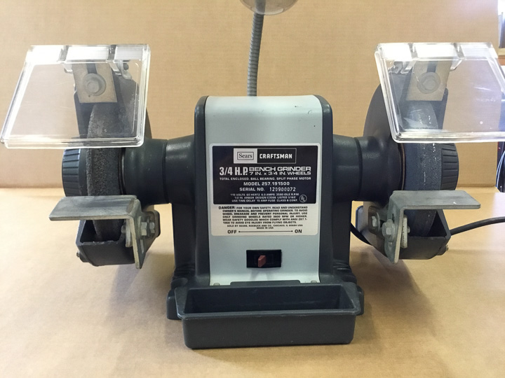
I purchased this new around 1981, it did not get a lot of use but it was there when I needed a grinder. It died when we moved from FL to OH about 14 years ago. I came close to just getting rid of it until I ran into this site via a web search.

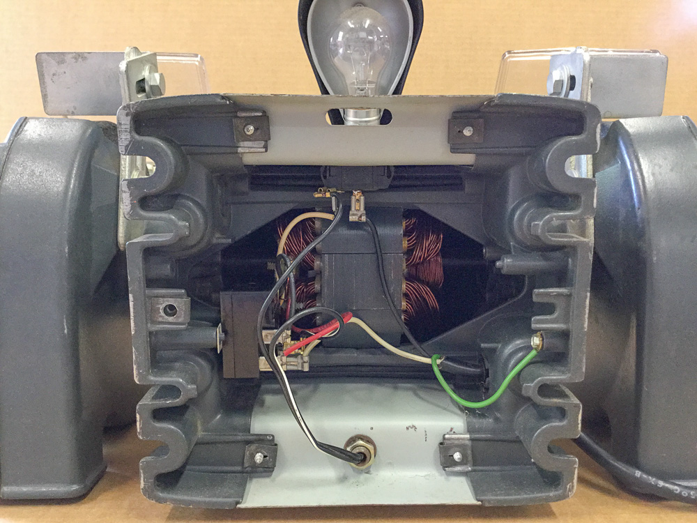
When you turn it on it makes the typical start up sounds and slowly starts to spin, but never gets up to speed. There is an 8 second video here:

http://vimeo.com/221165502/043a9e1b19

My gut tells me it might be the relay, but I am not sure. I took it apart and the contacts appeared to be clean, but I am not sure how to trouble shoot it to make sure it is working properly. I sure would like to this running again.

Thanks in advance for any help.
 
Last edited:
To avoid these ads, REGISTER NOW!

pendragon1998

Well-known member
Joined
Mar 24, 2012
Messages
3,733
Location
NE Georgia
I think it's probably the start capacitor, which kicks in to get it up to speed, then disconnects. Yours doesn't seem to be powering the start windings. If you run it with a bad one, you may burn up your windings. It's cheap to replace.
 
OP
C

Chiz

Active member
Joined
Jun 11, 2017
Messages
29
Location
Ohio
I think you came to the right place for help. Not by me though. Nice grinder.

Larry I certainly hope so, I have been impressed by most of what I have seen here thus far.

I think it's probably the start capacitor, which kicks in to get it up to speed, then disconnects. Yours doesn't seem to be powering the start windings. If you run it with a bad one, you may burn up your windings. It's cheap to replace.

Pendragon, this model did not come with a capacitor. I am the only one who has ever opened it up. Here is what it looks like:

IMG_0241.jpg


It is very similar (mine has the light wired in) to this one:

http://www.garagejournal.com/forum/showthread.php?t=104312&page=3
(about a 1/3 of the way down)

Thank you both for the replies.
 
Last edited:

BFBOB

Well-known member
Joined
Sep 20, 2011
Messages
5,073
General troubleshooting: It looks like there are two sets of windings sharing a common hot via the switch. Disconnect all three leads (take pix AND make drawings first!!!) and check for continuity with a multimeter. There should be pretty low resistance between any pair of those wires. If any pair of them is open, you've got a bad winding. If they all show continuity, you've got a bad relay/capacitor/switch - whatever that black box at the left is.
I've seen some motors that have a switch for the start windings that is normally closed, and opens via a centrifugal lever when the rpm's get up to running speed. I can't see from your picture whether that's the case here, or the black box is a thermal relay; opens the circuit when it heats up.
Others more familiar with this exact model will doubtless chime in; in the meantime, give your multimeter a workout!

Oh, and welcome aboard!
 
To avoid these ads, REGISTER NOW!
OP
C

Chiz

Active member
Joined
Jun 11, 2017
Messages
29
Location
Ohio
General troubleshooting: It looks like there are two sets of windings sharing a common hot via the switch. Disconnect all three leads (take pix AND make drawings first!!!) and check for continuity with a multimeter. There should be pretty low resistance between any pair of those wires. If any pair of them is open, you've got a bad winding. If they all show continuity, you've got a bad relay/capacitor/switch - whatever that black box at the left is.
I've seen some motors that have a switch for the start windings that is normally closed, and opens via a centrifugal lever when the rpm's get up to running speed. I can't see from your picture whether that's the case here, or the black box is a thermal relay; opens the circuit when it heats up.
Others more familiar with this exact model will doubtless chime in; in the meantime, give your multimeter a workout!

Oh, and welcome aboard!

BFBOB - Thank you for the compressive reply and directions. There is no centrifugal lever in this model, thus from what I understand the black box is a relay. The meter will get some exercise later today. I will keep everyone posted.

Well, that's what I get for trying to be smart :)

Pendagron - No such thing as a bad comment, it might prompt someone to think of something else.

By the way I have seen your woodworking vice thread and I am in the process of restoring my identical vice. It is getting an electrolysis bath currently. I am seriously considering painting mine the same as yours. I will check out your grinder restore.

That's pretty much the "Have you turned it off and on again?" from the IT world translated to working on electric motors. :lol:

Firworks, yep it has been turned on and off again, and I will add yes it was plugged in. lol!

Thanks!
 
Last edited:

6PTsocket

Well-known member
Joined
Mar 12, 2014
Messages
4,593
That device on the left in your picture is a start relay. It switches the start winding in and out. It is an alternative method to a centrifugal switch. Motors pull a lot of current on starting and it drops to the normal running current when the moror reaches full speed. The contact of the start relay connects the start winding. The relay is normally open. The coil of the relay is in series with the whole motor. When you turn the motor on, the high starting current instantly closes the relay and connects the start winding. As the motor speeds up, the current falls. At about 80% of full speed there is not enough current to hold the relay and it drops out, disconnecting the start winding. There is no capacitor or centrifugal switch. This is common on a lot of grinders. If it is the relay that is your problem, Sears no longer has the one you need. The one they say fits many grinders is for smaller current models. The relay coil must be sized correctly for the current rating of your motor. See the main block grinder thread for alternate sources. This, of course, only applies if it is the relay.

Sent from my SM-G900V using Tapatalk
 
OP
C

Chiz

Active member
Joined
Jun 11, 2017
Messages
29
Location
Ohio
That device on the left in your picture is a start relay. It switches the start winding in and out. It is an alternative method to a centrifugal switch. Motors pull a lot of current on starting and it drops to the normal running current when the moror reaches full speed. The contact of the start relay connects the start winding. The relay is normally open. The coil of the relay is in series with the whole motor. When you turn the motor on, the high starting current instantly closes the relay and connects the start winding. As the motor speeds up, the current falls. At about 80% of full speed there is not enough current to hold the relay and it drops out, disconnecting the start winding. There is no capacitor or centrifugal switch. This is common on a lot of grinders. If it is the relay that is your problem, Sears no longer has the one you need. The one they say fits many grinders is for smaller current models. The relay coil must be sized correctly for the current rating of your motor. See the main block grinder thread for alternate sources. This, of course, only applies if it is the relay.

Sent from my SM-G900V using Tapatalk

6PT - Thanks for the comprehensive how it works! It definitely helps me understand how this thing should work.
 
OP
C

Chiz

Active member
Joined
Jun 11, 2017
Messages
29
Location
Ohio
I was finally able to get a meter on this, see attached wire diagram below.
With the motor windings disconnected from the relay and switch, here is what I get:

White and Red = 10.1 ohms

White and Black = 1.2 ohms

Red and Black = 11.2 ohms

BFBOB stated that they should be “pretty low resistance”. I am not sure if these are normal values, but due to the size of the wire used in the windings (see pic above) I would guess they should be pretty low.

Thoughts please, Thanks in advance!

Wire%20Diagram%20%20257_191500.jpg
 
To avoid these ads, REGISTER NOW!
Top Bottom