To avoid these ads, REGISTER NOW!

help me fix my bench grinder

truckaddict

Well-known member
Joined
Nov 20, 2013
Messages
59
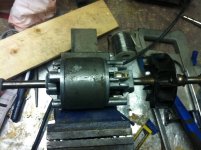
I will try to get some pics up once i figure out how. I have a Craftsman Electronic Variable Speed Bench Grinder. Permanent Magnet Motor. Model C257.205220.

The old girl stopped working. I'm 90% sure that what killed it is the circuit board. I called Sears, and not surprising that they don't have parts for it as its old. I tried fixing the circuit board but no go.

My thought is to skip the circuit board and hard wire the brushes, removing the variable speed, and adding an external speed control. When I took it apart I wasn't real careful about which wire, which brush so I tried all possible connections. All I have been able to get so far is tripping the circuit or the motor doing some vibrating and smoking. Is their anything someone can think of to get this old girl working.

Normally I would spend some money and get a new one by my wife will kill me if I buy anything else. Just bought a joiner, bench sander, random orbital, and a biscuit joiner and wood lathe chisels.
 
To avoid these ads, REGISTER NOW!

Craptain

Well-known member
Joined
Apr 18, 2013
Messages
4,028
Location
Tampa Bay FL
With a variable speed and permanent magnet motor I believe the board changes frequency applied to the motor. And the voltage will not be at mains voltage. So I am afraid that by letting the smoke out you have probably given it the kiss of death.
 

R.Anderson

Well-known member
Joined
May 26, 2012
Messages
906
Location
Wisconsin
Post pictures. Don't try hooking the motor up like that again, the motor is DC. The drive board converts AC to DC and pulses the dc for speed control. Post pictures of the drive board (top and bottom) and the motor and wires. If the motor is not dead its possible to rebuild the board or buy new or used drive board that will work. Do you have a soldering pencil and solder for electrical work?
 

R.Anderson

Well-known member
Joined
May 26, 2012
Messages
906
Location
Wisconsin
Would be nice to say Please as well :)

Please help me fix my bench grinder
instead of being kinda demanding
help me fix my bench grinder

you might of gotten more responses FYI

Make sure your pics are 800X600 or smaller.

Now go to where you type up a reply/comment. On the bottom of that Window you will see "post quick reply" and " Go Advanced" Click " go Advance"

Now the rely window has more options. In order to post a reply with pictures there needs to be text type " can't post a blank reply"

On to attaching pictures

Look up in the tool bar in the reply window you will see a "smiley face" and to the right of that there is a "paper clip" click on the "paper clip"

A new window pops up

click browse to find your pictures on your computer. you can attach up to seven pictures at a time this way. Once you have selected all the pictures you want to post click "upload" this may take a minute or so depending on size and quantity of pictures uploading. Once the picture are uploaded click "close this window" above all the browse buttons to the right.

Type your text and Click "preview Post" to make sure you have right pictures and it works. If it good to go scroll down to the edit window and click "submit reply"
 

larryq

Well-known member
Joined
Jul 12, 2011
Messages
2,421
Would be nice to say Please as well :)

Please help me fix my bench grinder
instead of being kinda demanding
help me fix my bench grinder

you might of gotten more responses FYI

FWIW I didn't get that vibe from his post.
 

Outlawmws

Well-known member
Joined
Aug 9, 2011
Messages
39,183
Location
The Badlands
I didn't get that vibe either...

Post some pics including post mortum.

I'm less concerned about the DC motor as many are AC/DC, and that is why they are variable. Not all mind you, but I'd bet on this one.

The board MAY be able to be replaced with a control board out of a treadmill...
 
OP
T

truckaddict

Well-known member
Joined
Nov 20, 2013
Messages
59
Thanks for the replies thus far. And sorry if I came off as demanding, not intended. I don't think its completely dead as the motor does move when you put power to it. This post should contain pics of the case motor and board. I do have a soldering pencil and fixed the bad connections on the board. I think its one of the components on the board.
 

Attachments

  • 1654465_10100334015183895_1533905100_n.jpg
    1654465_10100334015183895_1533905100_n.jpg
    85.7 KB · Views: 84
  • 1656071_10100334015129005_110455320_n.jpg
    1656071_10100334015129005_110455320_n.jpg
    83 KB · Views: 75
  • 1898064_10100334015243775_536169505_n.jpg
    1898064_10100334015243775_536169505_n.jpg
    138.1 KB · Views: 70

R.Anderson

Well-known member
Joined
May 26, 2012
Messages
906
Location
Wisconsin
FWIW I didn't get that vibe from his post.

Whats wrong with saying please? :dunno:
Almost three hours in and only two replies in the tools section is a little low for a Friday I think, Adding the word please in the title I think would bring in more responses. If I thought he was being demanding/rude I wouldn't of taken the time to post about the grinder and info on attaching pics.

If the driver board is whats bad and not the motor in the beginning, the attempts of bypassing the driver board would have worked if every combination of wiring it up was tried if it was AC/DC motor. Would it not?
 

jakemac

Well-known member
Joined
May 21, 2013
Messages
9,035
Location
New England
Once upon a time, some Radio Shack stores used to have testing equipment in the back room. I doubt that they provide that service any longer though. They don't provide much in store for the electronic DIY'er anymore. :dunno:
 

R.Anderson

Well-known member
Joined
May 26, 2012
Messages
906
Location
Wisconsin
Looks like a AC to DC driver board to me with those four diodes making a bridged rectifier. When you say "the motor does move when you put power to it" Move how? like the shaft vibrating back and forth. If you have a 12 car battery or other low voltage DC power supply (transformer battery charger should work) hook it up to the motor to see if it spins.
 
Last edited:
OP
T

truckaddict

Well-known member
Joined
Nov 20, 2013
Messages
59
not sure if it should work when wired up if its an ac/dc. It moves properly for about a half turn but then sparks or smokes.
 

R.Anderson

Well-known member
Joined
May 26, 2012
Messages
906
Location
Wisconsin
If you can make out the numbers and letters on this component post em if you could please?
 

Attachments

  • 1654465_10100334015183895_1533905100_n.jpg
    1654465_10100334015183895_1533905100_n.jpg
    90.2 KB · Views: 47

Outlawmws

Well-known member
Joined
Aug 9, 2011
Messages
39,183
Location
The Badlands
Both that transistor and the set of 4 diodes in the middle, (black/dark 2 lead parts with the light band at one end)


Exactly what sparks and smokes? Not a good sign...
 

Davefr

Well-known member
Joined
Jan 7, 2010
Messages
11,822
Location
OR
Have you checked the brushes to make sure they're OK?

The next step is to connect a voltmeter to the output from the rectifier and see what it reads while changing the speed control.

If it's bad, then remove the 4 diodes and transistor and test them out of circuit using the diode setting on your DMM.

You should also test that sliding potentiometer. It could be worn or dirty.
 

R.Anderson

Well-known member
Joined
May 26, 2012
Messages
906
Location
Wisconsin
That should be a triac(Triode alternating current switch) a type of thyristor/SCR but bidirectional used for controlling AC, not a transistor.

This is not the schematic for the Craftsman motor control pictured above
. Its just an example the type of AC to DC variable speed controller I think we are dealing with here.

---------------------------------
If the the springs on the brushes had enough amps pushed through them they will heat up and anneal and won't apply enough pressure. The very little contact of the brushes will cause excessive sparking/arcing and smoke. This has happened to one of my motors once.
 

Attachments

  • AC2DCdriver.JPG
    AC2DCdriver.JPG
    106.3 KB · Views: 28
Last edited:

volleyball

Well-known member
Joined
Aug 29, 2011
Messages
4,127
Location
NY, not NYC
Did you try fixing it by replacing the black component in the upper left of the first pic? Active components are most likely to fail.
 

coyotejake

Well-known member
Joined
Dec 18, 2013
Messages
93
Location
Washington state
We're men, we don't need 'please'. Just buy us all a beer, and we'll all get together and bring our hammers to come fix it for ya.
 

R.Anderson

Well-known member
Joined
May 26, 2012
Messages
906
Location
Wisconsin
We're men, we don't need 'please'. Just buy us all a beer, and we'll all get together and bring our hammers to come fix it for ya.

There are women on GJ, not many but they are in here just so ya know.

Not every one drinks, I don't and I sure there are others. So I'll take a rootbeer or cream soda if that the case:)

If you think you can fix this with a hammers lol good luck, brute force is not always the answer.

And again there is nothing wrong with saying please, odds are you will get further. Treat others as you want to be treated.

So kindly :stfu: :D
 
To avoid these ads, REGISTER NOW!

R.Anderson

Well-known member
Joined
May 26, 2012
Messages
906
Location
Wisconsin
Did you try fixing it by replacing the black component in the upper left of the first pic? Active components are most likely to fail.


Yup, this is the reason I asked for the ID info on what I believe to be a triac, to figure out how to correctly test it and to replace if found to be bad. This component does the work of controlling the speed of the motor and the potentiometer controls this. Theses two are the most likely to be the problem, then if not to the four diodes. Before going though all this the motor should be tested first to rule it out. Test first not just go replacing things, will save time, money and your nerves.

If you want, I'll draw up a schematic and come up with several tests for troubleshooting. Just post a clear picture of the back side of the board showing all the copper traces.
 
Last edited:

volleyball

Well-known member
Joined
Aug 29, 2011
Messages
4,127
Location
NY, not NYC
You were getting technical before you knew who you were dealing with. I have no idea of the OP skill level so I started simple. That is why I described it that way.
I was an electronics instructor in the Navy and I've learned to start simple. KISS
 

R.Anderson

Well-known member
Joined
May 26, 2012
Messages
906
Location
Wisconsin
You were getting technical before you knew who you were dealing with. I have no idea of the OP skill level so I started simple. That is why I described it that way.
I was an electronics instructor in the Navy and I've learned to start simple. KISS

"You were getting technical before you knew who you were dealing with." :confused:

The tech talk I posted about the triac? That was for those who were calling the component in question a transistor.

Your suggesting on replacing the one component would be easy and simple but I'm looking ahead here. So lets say he orders the new component (cost: part and shipping) and replaces it and it still does not work. So now after testing it was another component that was bad. Now he has to order another part (cost now: price of both parts and two shipping charges)

Guess you could order all new components and replace them all(guessing it would be way cheaper than buy a new board) and do away with the testing on the board but I still would test the motor.


"I was an electronics instructor in the Navy and I've learned to start simple." Good to know. Hows all that work in the NAVY? is there different levels of technicians or specialties for areas like radio, radar, power, or are the people that use the equipment trained? I have no clue on how that goes.
 
Last edited:
OP
T

truckaddict

Well-known member
Joined
Nov 20, 2013
Messages
59
Sorry I took a while getting back on here. The wife decided we had to go to her brothers place for the weekend, So off we went. The black component is labeled Q4015L9 across MEX vertically and AO at the bottom. In terms of my skill I'm capable when it comes to soldering, but have never worked on circuit boards and don't have any real knowledge as too what is what on them.
 

R.Anderson

Well-known member
Joined
May 26, 2012
Messages
906
Location
Wisconsin
There are several ways of going about this. Replace the parts in question, Rig/modify the board to be on/off without the variable speed and run full speed, or perform several test and find out whats wrong.

Out of these three I would consider going with rig/modify, I never needed or wanted to slow down the speed of my bench grinders.

----------------------------------------------
Replace the TRIAC here are two sources (there are others just search Q4015L5):

Q4015L5 should work. Q4015L9 seems to be obsolete and no longer made and I couldn't find any one that sold em.

http://www.mouser.com/ProductDetail...GAEpiMZZMuAO0%2bGuNbnQh2vcbv8QNstgN0x4MKhpBo=

http://www.ebay.com/itm/NEW-1x-Q401...V_Boards_Parts_Components&hash=item1e869e88a2

The sliding potentiometer I would need the value/part number off it before attempting to find one that will work. Might have to mount a regular potentiometer of the same value.

----------------------------------------------

Rigging/modifying

Solder a bridge between the two legs of the TRIAC marked TP3 and TP4. This should provide DC current to the motor at full speed as long as the four diodes on the board are good. If anyone sees a problem with this please point it out.

----------------------------------------------
Perform all tests with the board on a non-conductive surface.


Testing the sliding potentiometer with no power to the board.

On the back side of the board find the three soldered pins to the sliding potentiometer (two of em should be on the same trace)

Set the multimeter to read ohms to measure the sliding potentiometer the value should be marked on one of the sides. Place one test probe on one of the two solder pins and the other probe on the pin by itself. Sliding the potentiometer back and forth slowly, the ohm measurement should move up and down.
With any luck this should be fine, if not this is might be a ****** finding one with the same dimensions. Could install a regular same value potentiometer.

To test the TRIAC the board needs to be hot to perform these test.

If you are comfortable/willing to test this board hot here are three test for you can do. Use Extreme Caution when performing these test. With the bridge rectifier in this circuit DEADLY DC current is present if the board is working. This is very dangerous do not handle the board when performing these test. Before testing or applying power to the board don't connect the wires for the motor, these two wires are the ones to really watch out for, tape the metal terminals up so they do not make conductive contact with anything. Now as well as the taped off terminals, there are several spots on the board that should have dangerous DC current as well so do not handle the board when performing these test.

Use a multimeter set to measure 120vac, with a probe on each Test Point perform the three following.

1. TP1 and TP2 should read 120vac (This is to make sure there is 120vac and that the meter is working)

2. TP1 and TP4 should read 0vac (just to make sure)

3 TP2 and TP3 should read ?? - 120vac this should vary on the sliding potentiometer. (this is the main one of the three)

Again take Caution if performing these test.
 

Attachments

  • TEST POINTS 1.JPG
    TEST POINTS 1.JPG
    91.6 KB · Views: 25
Last edited:
OP
T

truckaddict

Well-known member
Joined
Nov 20, 2013
Messages
59
R.Anderson thanks for the instructions. Tomorrow I shall embark on the modifying method you outlined. I will let you know how I make out. And don't worry I will not electrocute myself.
 

volleyball

Well-known member
Joined
Aug 29, 2011
Messages
4,127
Location
NY, not NYC
There are several ways of going about this. Replace the parts in question, Rig/modify the board to be on/off without the variable speed and run full speed, or perform several test and find out whats wrong.

Out of these three I would consider going with rig/modify, I never needed or wanted to slow down the speed of my bench grinders.

----------------------------------------------
Replace the TRIAC here are two sources (there are others just search Q4015L5):

Q4015L5 should work. Q4015L9 seems to be obsolete and no longer made and I couldn't find any one that sold em.

http://www.mouser.com/ProductDetail...GAEpiMZZMuAO0%2bGuNbnQh2vcbv8QNstgN0x4MKhpBo=

http://www.ebay.com/itm/NEW-1x-Q401...V_Boards_Parts_Components&hash=item1e869e88a2

The sliding potentiometer I would need the value/part number off it before attempting to find one that will work. Might have to mount a regular potentiometer of the same value.

----------------------------------------------

Rigging/modifying

Solder a bridge between the two legs of the TRIAC marked TP3 and TP4. This should provide DC current to the motor at full speed as long as the four diodes on the board are good. If anyone sees a problem with this please point it out.

----------------------------------------------
Perform all tests with the board on a non-conductive surface.


Testing the sliding potentiometer with no power to the board.

On the back side of the board find the three soldered pins to the sliding potentiometer (two of em should be on the same trace)

Set the multimeter to read ohms to measure the sliding potentiometer the value should be marked on one of the sides. Place one test probe on one of the two solder pins and the other probe on the pin by itself. Sliding the potentiometer back and forth slowly, the ohm measurement should move up and down.
With any luck this should be fine, if not this is might be a ****** finding one with the same dimensions. Could install a regular same value potentiometer.

To test the TRIAC the board needs to be hot to perform these test.

If you are comfortable/willing to test this board hot here are three test for you can do. Use Extreme Caution when performing these test. With the bridge rectifier in this circuit DEADLY DC current is present if the board is working. This is very dangerous do not handle the board when performing these test. Before testing or applying power to the board don't connect the wires for the motor, these two wires are the ones to really watch out for, tape the metal terminals up so they do not make conductive contact with anything. Now as well as the taped off terminals, there are several spots on the board that should have dangerous DC current as well so do not handle the board when performing these test.

Use a multimeter set to measure 120vac, with a probe on each Test Point perform the three following.

1. TP1 and TP2 should read 120vac (This is to make sure there is 120vac and that the meter is working)

2. TP1 and TP4 should read 0vac (just to make sure)

3 TP2 and TP3 should read ?? - 120vac this should vary on the sliding potentiometer. (this is the main one of the three)

Again take Caution if performing these test.

I could not do this better. Now that we know that transistor is a triac and part #, your instructions make sense.

I thought about it and wonder if you think my stating I was a a know it all because I taught electronics, it was not my intentions. Decades of looking at glazed over eyes when talking tech means you talk as simple as the audience can handle.

To the OP, if you are uncomfortable, any electronics repair shop could do this for you or post a CL ad looking for someone. Going to a Radio Shack might find a person who can solder. It isn't hard but if you are unskilled, you could start lifting traces, which can be fixed by a piece of wire, which makes it harder to do.
 

R.Anderson

Well-known member
Joined
May 26, 2012
Messages
906
Location
Wisconsin
I could not do this better. Now that we know that transistor is a triac and part #, your instructions make sense.

I thought about it and wonder if you think my stating I was a a know it all because I taught electronics, it was not my intentions. Decades of looking at glazed over eyes when talking tech means you talk as simple as the audience can handle.

To the OP, if you are uncomfortable, any electronics repair shop could do this for you or post a CL ad looking for someone. Going to a Radio Shack might find a person who can solder. It isn't hard but if you are unskilled, you could start lifting traces, which can be fixed by a piece of wire, which makes it harder to do.

Thanks :beer:

OP said he was ok on the soldering part just the electrical component part he has trouble with.

Is there any "real" Radio Shacks left:sad: I quit shopping at the three in my area years ago. They pretty much turned into mini BestBuys.

" It isn't hard but if you are unskilled, you could start lifting traces, which can be fixed by a piece of wire, which makes it harder to do." Confused with this one, I know what you mean but as to what traces on this board?
 

volleyball

Well-known member
Joined
Aug 29, 2011
Messages
4,127
Location
NY, not NYC
I assume traces on the back side. I don't see any wires on component side. Or rivets to hold components in place.
 

volleyball

Well-known member
Joined
Aug 29, 2011
Messages
4,127
Location
NY, not NYC
Ok, what happens when an inexperienced person applies too much heat or not enough and tries to lift a component.
 

Outlawmws

Well-known member
Joined
Aug 9, 2011
Messages
39,183
Location
The Badlands
Not enough and nothing happens. "To much" depends on several factors. Thin traces lift easier than wide traces.

And he shouldn't be doing any de-soldering until he's mastered solder wick or a solder sucker or both...

Usually one sided boards like that in industrial equipment have fairly generous trace widths. At least until they get close to those leads on the Triac
 

R.Anderson

Well-known member
Joined
May 26, 2012
Messages
906
Location
Wisconsin
Ok, what happens when an inexperienced person applies too much heat or not enough and tries to lift a component.

Gotcha now:thumbup:, accidentally removing/damaging a trace.

This is the part that confused me:
"It isn't hard but if you are unskilled, you could start lifting traces, which can be fixed by a piece of wire, which makes it harder to do."

I was thinking you were saying remove traces on purpose for trouble shooting, practice or something. This was not making any sense why you would tell the OP to remove traces.
 

R.Anderson

Well-known member
Joined
May 26, 2012
Messages
906
Location
Wisconsin
Not enough and nothing happens. "To much" depends on several factors. Thin traces lift easier than wide traces.

And he shouldn't be doing any de-soldering until he's mastered solder wick or a solder sucker or both...

Usually one sided boards like that in industrial equipment have fairly generous trace widths. At least until they get close to those leads on the Triac

Not enough heat can lead to damage traces on single and double sided PCBs and SMT PCBs.
With some of the inexperience trying to remove a thru-hole component with not enough heat applied, some try to push it back and forth in attempt to remove it. In doing so can damage the trace. Even with the experienced accidentally pushing the component in a bit can damaged the trace, I know, I have done this several times.

You mean on this board right :) I know of only one way to master anything, that is by doing.

Ether way OP has opted to solder a bridge on the two legs of the Triac so there shouldn't be any de-soldering for the OP to do unless other problems reveal themselves.
 
Last edited:
OP
T

truckaddict

Well-known member
Joined
Nov 20, 2013
Messages
59
I got started today, but got side tracked by another project, opps. Didnt have any issues with the soldering except for a place where the trace had lifted (not sure if it was me or already happened). Like was said replaced it with a piece of wire. In terms of electronics to practice on this is it, too limited on storage area to keep things that are busted.
 

malibulvr

Well-known member
Joined
Jan 5, 2012
Messages
141
Location
Lockport, NY
Use a little flux on there, then you won't have to leave the iron on the component too long and lifting the trace.
 
OP
T

truckaddict

Well-known member
Joined
Nov 20, 2013
Messages
59
Im calling it boys, it is dead beyond repair. Spent enough hours on it, enough time thinking about it, time to cut my losses. Though please feel free to check out the soon to be posted, "Please help me source a part for my lathe"
 
To avoid these ads, REGISTER NOW!
Top Bottom