To avoid these ads, REGISTER NOW!

Help Save My Fixture Table

CDRomulan

Member
Joined
Apr 28, 2024
Messages
7
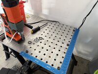
Long time lurker, first time poster. I recently bought a Primeweld Tig 225X and have been teaching myself to weld. I have gotten to point in my welding practice where it would be helpful to be able to clamp pieces down, so I began the process of turning the 24 x 36 x 3/8 inch hardox plate I've been welding on into a proper fixture table. I wanted to make drilling 216 holes as quick and easy possible, so I drew up a jig that would allow me to drill 5/8th inch holes on a 2 x 2 inch grid and had it laser cut in 3/8th mild steel by SendCutSend. The jig is designed to accept hardened drill bushings to reduce wear on the jig from the annular cutter I'm using to drill the holes. The jig indexes off the previously drilled row using four 5/8th shoulder bolts which also clamp the jib to the table. I thought using this jig would allow me to drill my fixture table as accurately as possible, but I've run into problems...

The Problem - After drilling the first seven rows of holes, I've realized that my rows are slowly drifting to one side. I lined up a carpenter square with the first row holes and determined that rows are a) not square with each other and b) have shifted 0.100" over the next six rows. This maths out to approximately 0.016" offset per row and 0.47 degrees out of square.

The Failed Solution - My first thought after realizing the problem is that the jig has some alignment issues due to cut tolerances of the laser cutter (allegedly 0.005") and thus the reference holes are slightly offset from the drill bushing holes. If this is the case then I should be able to flip jig over and the next rows of holes will move 0.016" to the left instead of the right like it had been. Nope. I drilled another row with the jig flipped, checked again, and now the overall offset is now .116".

What gives? If the reference holes were slightly offset then flipping the jig 180 degrees should have pulled the next row in the opposite direction. If it was issue with the jig being out of square in relation to the table then that should have translated to each row and they would be square relative to each other, but they are not. Where is the drift coming from? Any ideas on how to fix it?

Thanks!
 

Attachments

  • IMG_4871.jpg
    IMG_4871.jpg
    474.6 KB · Views: 115
  • IMG_4886.jpg
    IMG_4886.jpg
    818.8 KB · Views: 103
  • IMG_4887.jpg
    IMG_4887.jpg
    922.9 KB · Views: 114
To avoid these ads, REGISTER NOW!

cvairwerks

Well-known member
Joined
Aug 12, 2016
Messages
7,204
Location
Within hearing distance of Texas Motor Speedway
You've got several problems ganging up on you. First and foremost, your table plate edges are not straight and square to each other. Your drill jig is not straight and square. For the accuracy you need, it should have been cut oversize and then machined and the bushing holes bored and reamed. Next, a drill fixture, to be accurate, is never, ever, even to be considered, to be located by bolts. It will always be located by tooling pins or dowels and done so that it will hold location in at least two axis at all times. Lastly, you build a shed with a carpenter's square and not a precision tooling fixtue.
Don't take this as being down on you. If you've never dealt with precision, needing to hold toterances under .010" of an inch, you wouldn't know. Pop over to Fireball Tools and watch Jason's video on his drill guide for a much better understanding and some good visuals.
I'm doing this on my phone at lunch and not on my desktop at home, so I can't cut and paste any helpful web stuff in.
 

RoninB4

Well-known member
Joined
Jul 22, 2020
Messages
3,498
Location
Under My House
-I'm in agreement with the above post by @cvairwerks about the possibility of multiple variables working against you. The jig was a good idea but did you even verify/measure the jig layout itself for accuracy? Using a laser to cut referenced holes wasn't a good idea, nor would using a water jet either. The accuracy/tolerance of hole placement and even the hole diameter itself is in doubt until it's been checked. The machine used may have been capable but did the drawing specify tolerances? Was the operator of the day having a good day? Deviations from what you wanted begin to multiply with each new row until a cumulative error emerges. All work, whether you or outsiders did it, must be verified/checked before trusting it. A couple of things to consider:

1) How much clearance is in the holes that are being used to reference the next row of holes? Too much allows the jig to shift
2) The heads of shoulder bolts (or any fastener) are not necessarily concentric to the ground shoulder or the thread axis
3) The edges of your plate are not to be considered for reference until you've verified that they are indeed perpendicular
4) A carpentry square is only good enough for carpentry work. Do you know how to do a quick check for it being square? Takes 3 minutes.
5) Understand why this is a perfect example of "tolerance stacking" and why the accuracy order of magnitude (10x) that's expected will dictate which machining method will be used and why both are important in designing a jig or fixture. You've just seen why.

-There's really no point to hammering on you for what's already been done, welcome to the world of jig and fixture making. What you've done is created your own lesson for why guidelines and procedures are followed. So what to do now? I guess that depends upon what's important to you. The jig should be checked before further use of it, corrective machining is possible but that will cost more money. If the pattern of the 5/8 holes is all that's really important (should be) then the jig could be used as is but you'll have to position/locate the jig by hand for each new set/row of holes. That negates some of the ease/speed the jig was supposed to provide but it's already taking you off course by using the built-in progression capability. A "bump stop" clamped to one end of the jig (small angle bracket?) would ensure that the pattern is consistent along the Y axis (width) so you'd only need to hand position the jig along the X axis (length). If you really want additional machining to correct the jig maybe you should either post the drawing here or send it to me in a message for further advice. I applaud that you put some thought into doing this but you missed some very basic guidelines that you weren't aware of.

-Oh and one more thing. I'm not familiar with Hardox to be certain of the properties. I looked it up and found info extolling the wear/impact/machinability/etc. properties but not enough regarding post machining stability. With other steels there's a good possibility of internal stresses being released from machining and warp occurring, sometimes called the "potato chip" effect. With that many holes in the plate it may/may not end up as flat as you wanted it to. A 3/8 plate is not very thick for a larger plate like that. Perhaps someone else with direct experience with this material can offer some insight. Post what you want to do if you want more help.
 
OP
C

CDRomulan

Member
Joined
Apr 28, 2024
Messages
7
Perhaps I should describe my situation and define expectations for the project so we can find a sensible solution. I am an absolute total noob when it comes to doing anything with metal. I'm a professional rock scientist, so I'm used to working in a world where "probably", "approximately", "good enough", and "we really have no idea" are all perfectly acceptable tolerances. Believe it or not, there are USGS standardized mapping symbols for situations where you need to say "the rock type probably changes here, but we can't see it so we're just taking an educated guess"; the acceptable level of error here can be measured in miles. As everyone has correctly snuffed out, I obviously have absolutely no prior experience to the world of precision tooling or fabrication.

So why I am taking this project? I bought an $800 chinese welder so I could mess around in the garage after work, learn a useful skill, and maybe make some stuff that will be useful around the house or in my other hobbies. I could have bought a $150 fixture table from harbor freight and called it day, but I wanted to take on a project that would allow me to grow my limited skillset, play with my new welder, and hopefully make sometime a little sturdier than the HF table. Obviously the easy layout feature of a my fixture table will no longer be up to spec with the HF table, but it'll be good enough for who its for. If it turns I'm actually some tig welding prodigy and start taking on aerospace contracts, maybe I'll splurge on that HF fixture table.

With expectations for the table now established, how we can solve my alignment issues using only primitive shed building tools? My main concern, and the reason I originally made this post, is that at the current rate of offset, I will be losing a significant amount of material on one edge of the table as I approach the end. The original drilling jig was designed with the intent of having the center of the outermost holes being 1 inch from the edges of the table, minus whatever minor inconsistencies are indigenous to the original steel plate. I perceive this to be an issue because having less material makes the edge of the table more susceptible to bending if I ever need to use one of those holes to clamp down really hard on something. Having that long taper in edge width also looks tacky; I obviously wouldn't want to draw visual attention to the amateur mistakes I've made so far, the Misses might take my big dollar outdoor furniture contracts away if she notices!
 

cvairwerks

Well-known member
Joined
Aug 12, 2016
Messages
7,204
Location
Within hearing distance of Texas Motor Speedway
First thing I would do is simply stop, clear everything off and be prepared to do some quality measuring and calculating. I would get yourself a quality ruler/scale that is 24" or longer, and has either 5R or 16R graduations. Use 1/100th scale and be precise as you can. You need to dig back in the dark recess of the memory banks on setting up 3-4-5 triangles and using an ultra fine sharpie, starting from the other end, lay out a straight line at the edge distance you want, then do the same for the sides, but at 90 degrees to the straight line. You may need to adjust the pattern a little to keep from running off one side, but you need to make sure that the sides stay 90 degrees to the short line. Once you have this established, you can then measure and lay out the hole grid with the sharpie and verify it is where you want it. Wipe it all off and repeat til you have the way you want it and the angles and spacing are correct. Stop your pattern with about a 4" gap to the last row of the other holes. Now you need a pair of bushings for your holes for small diameter bits... Drop them in the end holes and center them on the grid. When you have it right, clamp it tight and recheck, then check again. Once you are satisfied with the alignment, without removing the bushings, center punch the holes and check the alignment again. Satisfied with it, then drill the small holes and keep a bit in each hole after drilling to keep things centered. Drill the next hole with the big bushing and insert a full size pin to lock that end of the tool. Repeat on the other end. Once you have the ends locked, drill the rest of the holes and then go back and do the end holes to full size. Move your tool up a row, lock it in place with bushings and pins and clamps and drill away. Make sure you are centered on your grid before drilling each row, and if not, correct it then.
I'd leave the 4" or so gap between the groups of holes and remember that one end is more accurate than the other and press on. About the best you can hope for, without a jig bore or optical tooling assist is in the .020-.030" range, which is plenty good for most work.

Yeah, it's going to be tedious and time consuming, but making an accurate tool takes time. Some of our drill fixtures at work, take more than 100 man hours just to locate the bushings for the drill guides, and we work to tolerances under .010" on our drill tools.
 

gte718p

Well-known member
Joined
Mar 12, 2009
Messages
3,972
I wouldn't stress about it. Unless you are doing production work, the holes are there to clamp fixtures not make alignments. I mean it is helpful to be able to align off, but its not a requirement.

You can build your own jigs using things like fireball tools adjustable clamps. It means layout will take a little longer, but odd are your stock is never going to fit the grid perfectly so you were going to have to adjust anyway. You first piece on the table defines straight. Everything else is relative to that. The hole spacing could be entirely random and it would not make a difference.
 

slowtwitch73

Well-known member
Joined
Apr 18, 2019
Messages
5,876
Location
Hellgate
It will still be flat (hopefully) and be able to clamp stuff down which is the vast majority of table utility.

Now if you plan on fixturing on it and building complex repeatable assemblies.. not so much. Even so you could do it, but would need to take errors into account.
 

OccupantRJ

Well-known member
Joined
May 15, 2009
Messages
10,989
Location
Eastern North Carolina
Unless you are going to exclusively weld on the table you might reconsider and stop at a partial drilling. You can clamp and square by using the holes you have already. I have a 4x8 foot table along with a mag drill and I have not drilled mine. I use my table as a fabrication, welding, tear down and rebuild bench and do not want to be risking dropping small items through the holes to escape, or get things hanging up while being slid around. You can always bridge clamp by using a piece of steel placed across the width of the table with a clamp on each end, or use standard clamps at the edges. Sometimes the reality of use overrides the perception.
 

Attachments

  • EC4F5B7F-25D0-4325-B02C-40803D7D1B80.jpeg
    EC4F5B7F-25D0-4325-B02C-40803D7D1B80.jpeg
    540.4 KB · Views: 78

RoninB4

Well-known member
Joined
Jul 22, 2020
Messages
3,498
Location
Under My House
With expectations for the table now established, how we can solve my alignment issues using only primitive shed building tools?
-Lots of great things from antiquity were constructed with "primitive" tools. Your results will have a direct correlation to the amount of time and care you're willing to put into what remains to be done.
My main concern, and the reason I originally made this post, is that at the current rate of offset, I will be losing a significant amount of material on one edge of the table as I approach the end.
-Reread my previous post, you can establish a Cartesian Grid that only needs to be hand set in one axis, the other axis will be provided courtesy of a bump stop attached to your fixture. Do the measuring, the math for the layout, clamp the fixture and you'll have acceptable results that will have the rows/patterns look uniform/consistent.
I perceive this to be an issue because having less material makes the edge of the table more susceptible to bending if I ever need to use one of those holes to clamp down really hard on something.
-A 3/8 plate isn't something you can expect to remain flat with all those holes and large clamping forces applied. Which brings me to another topic. What do you plan to do with 5/8 holes? If you're planning on tapping those holes for 3/4 threads then you need to rethink that. Even a type of screw clamp that uses a 5/8 hole for pass through clearance will exert enough clamping force to deflect a 3/8 thick plate. I would suggest a 1/4 - 5/16 screw would be sufficient for your projects. Anything requiring more clamping force than that would need a more robust welding table. Installing drill bushings of smaller ID will allow you to use your fixture. Do not compare what you're trying to accomplish with Harbor Freight products, Harbor Freight is the low bottom end of minimal expectations for almost everything they sell. Nothing wrong with using things purchased there, but exceeding things they sell should be what to strive for and an easily attainable goal.
Having that long taper in edge width also looks tacky; I obviously wouldn't want to draw visual attention to the amateur mistakes I've made so far, the Misses might take my big dollar outdoor furniture contracts away if she notices!
-Understandable why you want it to look properly done. The suggestion from @cvairwerks about using a Sharpie was good but it should be used to create a small black background patch at a given location You then take an awl, scribe, or even a nail sharpened to a fine point to draw a layout mark that will appear silver (steel) against the small black patch from the Sharpie. A line from a Sharpie is at least 1/16 wide, a sharpened scribe creates a line only .003-.010 wide. Which do you think will allow for greater accuracy? I used this method a lot on the job for precision machining, preferring it over Dykem layout fluid. You only need to layout where one hole per row will be and don't need to center punch either. If you do the math and locate your jig carefully by hand, clamping in place will provide the same pattern you wanted with minimal layout. What may be simple to me after 40 years in machine shops may not sound simple to you because I've worded my explanation poorly. If none of this made sense do say so and I'll try to explain better.
 
Last edited:

zimman

Well-known member
Joined
Mar 2, 2014
Messages
2,085
Location
Mark Twain National Forest
Perhaps I should describe my situation and define expectations for the project so we can find a sensible solution. I am an absolute total noob when it comes to doing anything with metal. I'm a professional rock scientist, so I'm used to working in a world where "probably", "approximately", "good enough", and "we really have no idea" are all perfectly acceptable tolerances. Believe it or not, there are USGS standardized mapping symbols for situations where you need to say "the rock type probably changes here, but we can't see it so we're just taking an educated guess"; the acceptable level of error here can be measured in miles. As everyone has correctly snuffed out, I obviously have absolutely no prior experience to the world of precision tooling or fabrication.

So why I am taking this project? I bought an $800 chinese welder so I could mess around in the garage after work, learn a useful skill, and maybe make some stuff that will be useful around the house or in my other hobbies. I could have bought a $150 fixture table from harbor freight and called it day, but I wanted to take on a project that would allow me to grow my limited skillset, play with my new welder, and hopefully make sometime a little sturdier than the HF table. Obviously the easy layout feature of a my fixture table will no longer be up to spec with the HF table, but it'll be good enough for who its for. If it turns I'm actually some tig welding prodigy and start taking on aerospace contracts, maybe I'll splurge on that HF fixture table.

With expectations for the table now established, how we can solve my alignment issues using only primitive shed building tools? My main concern, and the reason I originally made this post, is that at the current rate of offset, I will be losing a significant amount of material on one edge of the table as I approach the end. The original drilling jig was designed with the intent of having the center of the outermost holes being 1 inch from the edges of the table, minus whatever minor inconsistencies are indigenous to the original steel plate. I perceive this to be an issue because having less material makes the edge of the table more susceptible to bending if I ever need to use one of those holes to clamp down really hard on something. Having that long taper in edge width also looks tacky; I obviously wouldn't want to draw visual attention to the amateur mistakes I've made so far, the Misses might take my big dollar outdoor furniture contracts away if she notices!
I think you're fine. Unless you are prepping machines for the space shuttle.
What are you using this table for? Tooling can be moved and adjusted to almost anything if your jig does not lay perfectly.
Zim
 

Jswain

Well-known member
Joined
Apr 26, 2013
Messages
2,457
Location
Calgary, AB
Man. Just keep on drilling the holes you have half of them done now. Your mag drill chuck isn't a precision object, the fixture you had lasered has some error, the annular cutter may not be perfect...but the good news is nothing you ever weld will be either, with or without a perfect table.

You would also have to check your square, with a precision square or using math to ensure it is also accurate. You can adjust them by tapping with a punch on the inside corner to close it up or outside to open etc...

Once you are finished take some square tube. Clamp it down tight as you can absolutely mfing perfectly square and weld them together.

Now once it cools it won't be absolutely perfectly square. The heat will distort the metal more then you clamping it down accurate to the .010". In fact, if you want it very good and you start with a perfectly square setup people will intentionally shim it out of square in favor of the direction they know it will pull.

DIY guy needing a table that is square measurable with anything finer then a tape measure is like needing a Bugatti to go to MacDonald's for supper.

You are doing a hell of a job and you will love the table. Don't sweat it not being perfect. I scribed mine, hole punched and drilled without a jig using just a mag drill and I absolutely love it.
 

strength_and_power

Well-known member
Joined
Apr 26, 2015
Messages
1,398
For being able to clamp pretty much anywhere on the table, you are good. To use the holes as a straight or square reference, not so good.

I wouldn’t sweat it. People have done more with less. If you end up using it frequently and it becomes a limiting factor, upgrade and use it for something else.
 

cvairwerks

Well-known member
Joined
Aug 12, 2016
Messages
7,204
Location
Within hearing distance of Texas Motor Speedway
Ronin: The scribe definite would be more accurate on doing layout, but remember, we are moving OP's understanding of accuracy at least 5 digits to the right of what he normally works with. Too much at one shot can lead to mental overload and project paralysis. We want him to be able to considerably improve his ability for accuracy without being overwhelmed and giving up on it. Small steps grasshopper..... :)
 

RoninB4

Well-known member
Joined
Jul 22, 2020
Messages
3,498
Location
Under My House
Ronin: The scribe definite would be more accurate on doing layout, but remember, we are moving OP's understanding of accuracy at least 5 digits to the right of what he normally works with. Too much at one shot can lead to mental overload and project paralysis. We want him to be able to considerably improve his ability for accuracy without being overwhelmed and giving up on it. Small steps grasshopper..... :)
-You're quite right about that, just wanted to start the OP off with good habits. The OP describes himself as a genuine "rock scientist" and I would hope that means being able to read a scale (ruler) and grasp what a Cartesian Grid is. If not it's time to learn. I agree that too much information risks swamping the OP. I tend to do that when posting or teaching and need better skills for both. Thanks for the reminder.
 

OccupantRJ

Well-known member
Joined
May 15, 2009
Messages
10,989
Location
Eastern North Carolina
As RoninB4 said, a dark background with a scribe mark improves layout and marking accuracy. I also use a black marker most of the time for background even though I have spray Dykem for larger areas. I use an Exacto knife as a scribe on some markings as it allows getting up closer to a rule or square for marking. It makes for a crisp mark on the dark background. For a person not requiring extreme accuracy a piece of pegboard makes a nice grid in one inch increments by marking through the holes with a transfer punch or marker, unless there is such a thing as metric spaced pegboard.
 

KwikFab

Well-known member
Joined
Jul 27, 2024
Messages
1,173
Location
Central Valley, CA
If accuracy throughout the entire table top is important, just purchase a fixture table.

I had a buddy that drilled out his own with a mag drill and he absolutely hated all the work he put in; he swore he'll just buy one next time.
 
To avoid these ads, REGISTER NOW!

Jswain

Well-known member
Joined
Apr 26, 2013
Messages
2,457
Location
Calgary, AB
If accuracy throughout the entire table top is important, just purchase a fixture table.

I had a buddy that drilled out his own with a mag drill and he absolutely hated all the work he put in; he swore he'll just buy one next time.
If you hate putting in work fabricating, then I don't think an expensive fixture table is for you...

Took me ~3 hrs to mark and drill mine ~48" x 48".
 

larry_g

Well-known member
Joined
Apr 28, 2007
Messages
16,874
Location
oregon
First thing I would suggest to the OP is to stop where your at with drilling holes. Use what you have understanding that the hole pattern you have is not correct and each setup you do will have to be squared using other means to get the project square. Buy a few cheap feeler gage sets and use them as shims against the pin/bolt in the hole to get things setup. I think at your stage in the learning curve and projects you may be doing that you can make this work for awhile until your skills and volume of work demand that you have a better and more precise table. Once you are skilled enough and the limits of the table are holding you back then you have the skills to know what is needed in your next table.

lg
no neat sig line
 
OP
C

CDRomulan

Member
Joined
Apr 28, 2024
Messages
7
Thanks for the replies everyone, after reading everyone's advice and then stepping away from the project for a few days, I think I'm in a better spot than I initially thought.

A few general notes to clear up questions/concerns from multiple people - the framing square was indeed checked for square when I bought it a while back and a quick recheck confirms it is still square. The tabletop was also carefully checked for square before the start of drilling using both the framing square and by carefully measuring diagonals. Table edges were checked with a Kreg straight edge and I was quite pleased to find that they were still perfectly straight even after I smoothed out the plasma cut edges with a flap disc.

Next steps - I think I'm going to go forward with Ronin's suggestion of using a bump stop and setting the row spacing by hand. One side of the jig now overhangs the edge of the table slightly, I might try tacking on a piece of scrap to the bottom of the jig to use as a bump stop. The edges are straight enough that this should work well, but I'll have to run the jig down the table while scribing a line just to be sure. I'll post an update once I get back to working on the tabletop.
 
OP
C

CDRomulan

Member
Joined
Apr 28, 2024
Messages
7
-A 3/8 plate isn't something you can expect to remain flat with all those holes and large clamping forces applied. Which brings me to another topic. What do you plan to do with 5/8 holes? If you're planning on tapping those holes for 3/4 threads then you need to rethink that. Even a type of screw clamp that uses a 5/8 hole for pass through clearance will exert enough clamping force to deflect a 3/8 thick plate. I would suggest a 1/4 - 5/16 screw would be sufficient for your projects. Anything requiring more clamping force than that would need a more robust welding table.
Strong hand tools instera clamps and inserta pliers. https://www.stronghandtools.com/products/inserta-clamps. They're reasonably well built but they're definitely a lightweight clamp; only rated for 300 lbs clamping pressure. If I ever need to apply significant clamping forces, I've got a selection of large f-clamps and c-clamps I can use. 99% of the time I'll be working with thinner materials, mostly 14 to 18 gauge steel and aluminum, I suspect the table will hold up to the clamping forces required for that just fine, but that might just be my inexperience talking.

You asked about why I chose 3/8th hardox earlier in the thread. I chose 3/8 because it seemed to be a frequently recommended thickness when I was looking at other peoples' builds online. It's a balance between 1/4" which is too lightweight and 1/2" which is heavier than I can easily handle by myself. The plate itself was found at the local steel surplus, it was already 24 in wide so they only had to cut it to length and it was also new enough that it hadn't developed any surface rust. I had no idea I had bought hardox plate until I brought it home and started googling to figure out why the bright red powdery coating was so hard to remove. I suspect its one their softer grades, either 400 or 450 because it scratches with a scribe more easily than my AR500 targets do.
 
OP
C

CDRomulan

Member
Joined
Apr 28, 2024
Messages
7
but remember, we are moving OP's understanding of accuracy at least 5 digits to the right of what he normally works with.
This made me laugh way harder than it should have, thanks for that. I'm not quiet as inexperienced with holding tight tolerances as I've led you to believe. My master's thesis project involved cutting and grinding .25" diameter rock cores to .500" ± .010 with the two faces of the cylinder ground to within .001" of parallel of each other. Grinding was done by hand with the rock core clamped in a starrett V-block and ground on a lapidary table with 600 grit silicon carbide powder. I then had to cut and grind two aluminum oxide rods to length using the same method to the same tolerances. All of this just to squish rocks like they're playdoh at 1500°f and 225,000 psi confining pressure. A mitutoyo digital micrometer was my single most used tool in grad school.
 

KwikFab

Well-known member
Joined
Jul 27, 2024
Messages
1,173
Location
Central Valley, CA
What do you suspect you'll be making to require such accuracy?

If it's simply "I want it to be precise" that's enough justification really, but I'm just curious.

I would just buy a fixture table and run with it if you value accuracy between each and every hole.

I'm all for "DIY" as I've posted about lots of projects myself in various threads, but some things are better left for others to take care of and trust me I've gone the DIY route with fixture tables myself before I decided to just buy a couple.
 

RoninB4

Well-known member
Joined
Jul 22, 2020
Messages
3,498
Location
Under My House
Strong hand tools instera clamps and inserta pliers. https://www.stronghandtools.com/products/inserta-clamps. They're reasonably well built but they're definitely a lightweight clamp; only rated for 300 lbs clamping pressure. If I ever need to apply significant clamping forces, I've got a selection of large f-clamps and c-clamps I can use. 99% of the time I'll be working with thinner materials, mostly 14 to 18 gauge steel and aluminum, I suspect the table will hold up to the clamping forces required for that just fine, but that might just be my inexperience talking.
-Ahh those clamps and not toe clamps. Quick to employ and remove, not too high a clamping force either. I would resist the urge to use anything but fingers to tighten the clamps, no cheater pipes. The table will survive but the question is whether it will begin to deflect/warp under multiple load points with all those holes in it. I can't say for certain either with those clamps but if a flat plane (table top) is important I'd put an indicator or machine straight edge on it while applying clamping forces. Some materials deflect/warp easier than others and I haven't worked with Hardox.
You asked about why I chose 3/8th hardox earlier in the thread. I chose 3/8 because it seemed to be a frequently recommended thickness when I was looking at other peoples' builds online.
-I understood that after reading the website. It may be acceptable for their expectations too, not knocking the choices of others. Some folks feel that 1/4" plywood top and 2x4's make a good work table for their expectations and probably can. Expectations should lead purchase choices, not the other way around. If it works for what you want it to do/be then you've made a good choice.
It's a balance between 1/4" which is too lightweight and 1/2" which is heavier than I can easily handle by myself.
-That's always a big consideration, how much weight can I realistically handle? I once found an abandoned piano in the alley (Chicago). I so very badly wanted just the sounding board from it but found it too heavy for me to lift. I left it there in the alley and still wish I had gotten it now 35 years later. Working within your physical limits that don't overload your body is best and a smarter decision than when I was younger and didn't make smarter decisions.
The plate itself was found at the local steel surplus, it was already 24 in wide so they only had to cut it to length and it was also new enough that it hadn't developed any surface rust. I had no idea I had bought hardox plate until I brought it home and started googling to figure out why the bright red powdery coating was so hard to remove.
-I'd call that a lucky break and I probably would have grabbed that too. Only you will know if the amount of metal removed by your hole pattern will make a difference or not.
I suspect its one their softer grades, either 400 or 450 because it scratches with a scribe more easily than my AR500 targets do.
-Did you get the hole jig problem worked out?
 
OP
C

CDRomulan

Member
Joined
Apr 28, 2024
Messages
7
What do you suspect you'll be making to require such accuracy?

If it's simply "I want it to be precise" that's enough justification really, but I'm just curious.
Absolutely nothing. I tend to be a perfectionist even when I don't need to be, but I'm willing to adjust my expectations when I recognize that the payoff isn't worth the effort/money/time/etc.

I will definitely just buy a fixture table if I ever need something bigger or more accurate in the future. It's worth the expense to avoid drilling hundreds of holes again.
 
OP
C

CDRomulan

Member
Joined
Apr 28, 2024
Messages
7
I was getting set up to tack weld a bump stop to the jig when I came up with one last idea to try. I previously assumed that a misalignment between the jig's reference holes and drill bushing holes was the cause of my offset, and tried flipping the jig over to see if that would shift the next row in the opposite direction. That solution did not work. Tonight I realized that if the jig is always drifting in the same direction, then flipping the table over and drilling from the bottom side should shift the next row away from the edge rather than towards it. I drilled one test hole to see what would happen, and what do you know, it worked.

This result has me thinking that the main culprit for my offset might be the drilled holes themselves. By my math, it would only take a 1.2 degree offset from vertical to cause a .016" lateral shift in the jig's alignment. Unfortunately I don't have any sort of reliable means of measuring the angle of the drilled holes or the mag drill chuck, but I wouldn't be surprised at all if my $200 chinese mag drill wasn't drilling perfectly vertical.

I'm currently on row 9 of this table, meaning I'm halfway there. While it's going to be annoying to flip the table over after every row, doing that should allow me to keep the remaining rows tracking straight while maintaining the speed and convenience of the jig. There will be a zig-zagging offset between the remaining rows doing it this way, but that offset is small enough that I'm not worried about it.
 

Jswain

Well-known member
Joined
Apr 26, 2013
Messages
2,457
Location
Calgary, AB
You could adjust the gib on the mag drill. Looks like it is holding its own weight up so it must not be that sloppy tho.

A metal square against the Weldon holder should get it set square enough. 1-2-3 block would be better if you have one.
 

Bigblue&Goldie

Well-known member
Joined
Mar 12, 2009
Messages
10,672
Location
AZ
Personally, I'd leave it as is. You have half of it for clamping and half for general work. Any setup you do you will want to align/square up independently from the holes in the table. My 2'x3' table was laser cut and I don't rely on it for accurate setups due to the nature of the hardware that goes in those clamps. Like others have said, unless you are a very skilled welder, resulting warpage far offsets any perceived issue your table might cause. I actually made/use a "pallet" when I need to hold tighter specs.

The most valuable part of my manual machining courses was the instructor handing us a drawing, having us make the part to spec, and then taking our part and showing how "off" it really was. I figured the surface grinder project would be cake......what an eye opener that was!

20190804_145003.jpg
20190804_140135.jpg
 

niget2002

Well-known member
Joined
Oct 2, 2012
Messages
11,123
Location
Josephine, TX
I'm also a newb to welding. My 'fixture table' has slots. All I need at this point is something flat I can stick clamps on. I did buy some of the fireball clamping fixtures that I can use to make things square to each other or to the table.
 

1redTA

Well-known member
Joined
May 17, 2006
Messages
730
Location
Pace FL
I like my diy TMR table, I don’t have the patience (or mag drill) to layout and drill all the holes, good on you
 

Bigblue&Goldie

Well-known member
Joined
Mar 12, 2009
Messages
10,672
Location
AZ
-Ok you've got me curious now. Why was the surface grinder project not easy? Photos are also appreciated.

Sorry, no pics as it was years ago. We had to grind a cube as perfect as possible. We all learned valuable lessons about cleanliness, dressing the wheel, etc. It seemed so easy; plop the metal on the magnetic chuck and wear your arm out! Nope! I remember handing my cube to the instructor and he put a dial indicator on it and ruined my day!
 
To avoid these ads, REGISTER NOW!
Top Bottom