To avoid these ads, REGISTER NOW!

Help troubleshooting rotary phase converter

tolken4

Well-known member
Joined
Nov 5, 2007
Messages
330

That is a link to a video of what I get. Power it up and I get a hum. Button does nothing. I have checked and triple checked wiring, but anything is possible I guess. This is a American rotary phase converter system. 5 hp baldor motor purpose supplied for this system. All parts are rock stock. Wire is 10awg 1 phase and 12awg 3phase. On a 40amp circuit.

Your help is appreciated. This is the only thing preventing me from first start up of my Rivett 608 lathe ;)
 
To avoid these ads, REGISTER NOW!

Steve from Socal

Well-known member
Joined
Jan 27, 2009
Messages
3,566
Location
Hutchinson Ks.
Is the potential relay closing ? The relay should add capacitance and phase shift to start the idler. If the relay is closing check the start capacitors.

Steve
 

larry_g

Well-known member
Joined
Apr 28, 2007
Messages
16,933
Location
oregon
Has this converter ever worked?
Has there been a recent move or modification?
Has the converter worked in this place and has just now quit?
Have YOU ever seen it run and used it?

What is your experience in checking electrical circuits?

Give us something to work with here other that what you have.

lg
no neat sig line
 
OP
T

tolken4

Well-known member
Joined
Nov 5, 2007
Messages
330
Good questions and sorry I left that bit out. For the purposes of troubleshooting, everything must be considered suspect including my wiring and the unit itself. Let me explain.

This was bought gently used, and I mean gently, off Craigslist. I have every reason to believe it is in working order. It was used for one project and then sold. The gentlemen was about as trustworthy as you can get from Craigslist. I truly believe the unit is like new and in working order and was working when he disconnected it. However, again, for hte purposes of troubleshooting, I have never actually seen this working, and I just wired it up myself after having it sit in my garage boxed up for a few years.

So the unit itself and my setup must be considered in play for the purposes of trouble shooting. I am not adept at electrical circuits, but I can troubleshoot basics.

WHAT I BELIEVE TO BE TRUE:

1. I have 240 across L1 & L2.other than that i can't promise anything.

2. I have the motor configured as specs for low voltage. Double checked and wires and numbered so this is pretty straight forward.

3. I have the load side disconnected to ensure it is not pulling before the idler starts.

4. WIRING:
Single Phase: I have single phase coming in to l1 &l2 & ground.
Idler: I have the idler to a, b, and c. And ground
Load: I have the load to L1,L2, and T3 and ground.

5. Switch is color coded so again as reasonably sure as can be that it is wired correctly.

6. When I apply power to the box it hums for a second then stops. and then nothing when I press the button.

How does one test these capacitors with a multi meter? I believe it involves the capacity to setting and watching the climb?
 
Last edited:

matt_i

Well-known member
Joined
Mar 14, 2008
Messages
10,828
Location
SE Michigan
So what could be the problem, is the starting capacitor is not supplying any energy to the 3rd leg of the idler. If you just power the idler on a single phase, from a dead start, it will sit there and hum. Either leg of incoming L1, L2 is paralleled thru a capacitor to L3, and usually a relay contact available to switch the L3-connected capacitor in and out of the circuit.

So a couple issues, the relay is not sensing correctly, its coil should be from L1-L3 or L2-L3, probably on the opposite pole as the relay contact. I really like a timing relay in this app (timer on delay) but its more expensive and didn't come with this package originally.

Best thing to check is to hook a voltmeter to either L1-L3 or L2-L3 via alligator clips so its hands off and you just touch the start button. You want to ramp from zero volts at rest to some other value, could be 190vac to 240vac, not sure.
 
OP
T

tolken4

Well-known member
Joined
Nov 5, 2007
Messages
330
Thanks Matt. I will check it out. One question I have been wanting to know is this. What is the exact deal on capacitors. I know they can hold a charge and bite. Manual says wait 30min. Is there a way to charge these down safely in a situation where you are short cycling this system to repeatedly test it after powering it up?
 

wyliesdiesels

Well-known member
Joined
Aug 14, 2012
Messages
20,280
Location
Modesto, CA
Sounds like a start capacitor issue.

Have u tried spinning the idler shaft when its humming/trying to start?

If u spin it and it spins up, then u got a start capacitor or start circuit issue.

Yes caps can be tested with a multimeter... Do u have one and if so ehich model?
 

matt_i

Well-known member
Joined
Mar 14, 2008
Messages
10,828
Location
SE Michigan
The resistor across one capacitor is a "bleed" resistor, likely this is the starting cap. This "bleeds" off excess energy by shorting it with a measured (small) current flow. The other two are likely running caps, to attempt to balance the voltages at a certain load. Just measure DC voltage across the capacitor to see what you are up against. A capacitor works a little differently on AC with the switching polarity, its not quite the pure storage bucket of a DC system.
 
OP
T

tolken4

Well-known member
Joined
Nov 5, 2007
Messages
330
Sounds like a start capacitor issue.

Have u tried spinning the idler shaft when its humming/trying to start?

If u spin it and it spins up, then u got a start capacitor or start circuit issue.

Yes caps can be tested with a multimeter... Do u have one and if so ehich model?

This is a purpose built Baldor motor. No, external shaft and the ends have internal screens that make spinning it not simple. I here no real hum at all from the motor.
 
OP
T

tolken4

Well-known member
Joined
Nov 5, 2007
Messages
330
The resistor across one capacitor is a "bleed" resistor, likely this is the starting cap. This "bleeds" off excess energy by shorting it with a measured (small) current flow. The other two are likely running caps, to attempt to balance the voltages at a certain load. Just measure DC voltage across the capacitor to see what you are up against. A capacitor works a little differently on AC with the switching polarity, its not quite the pure storage bucket of a DC system.

Make sense on the resistor. I had wondered if that was its purpose. Can you be more specific on the DC testing of the Capacitor?
 

johnbennetch

Well-known member
Joined
Aug 18, 2015
Messages
67
Location
Carlisle Pa
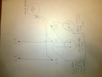
I used to build these from scratch. This is the basic principles of the system.
 

Attachments

  • WP_20150927_002.jpg
    WP_20150927_002.jpg
    140 KB · Views: 39

johnbennetch

Well-known member
Joined
Aug 18, 2015
Messages
67
Location
Carlisle Pa
When we would build them, you would add or subtract run caps until you would get a good balance of amps on the motor of the equipment. The principles of how it works is that the cap. gives a opposite wave in the sign wave as line two. If you would use a oscilloscope line 1 and line 3 would look very similar. But the idler motor is like a generator in that the windings of the motor skew the sign wave to the proper 1/3 step for each leg. And it also takes the harsh edge off the cap. discharge and inrush. The start cap is the kick in the pants that is needed to get line 3 to raise the inrush like the other legs and get all the motion started. A potential relay is closed by the inrush of the start but the spring tension will open the relay when the amps drop. It actually has the load of line two running through the coil. That is how it can open when it starts because it actually is monitoring the motor load.
 

Dagny

Well-known member
Joined
Jul 25, 2014
Messages
3,075
Location
Northern Wi.
I know some will argue but I have been shorting across the terminals with a screwdriver for years to discharge capacitors. But I keep several of each size in my service truck. It is best to use a capacitance meter to test them. Second choice is analog ohm meter. Put it at highest setting discharge capacitor then hook test leads one on each terminal needle should swing to right then slowly swing left as the cap. charges.
 

LutzTD

Well-known member
Joined
Dec 31, 2011
Messages
3,673
Location
Lutz, Florida
those guys are still in business, did you try giving them a call? Or just get the support literature and make sure its all wired correct.

I have the same 5hp unit and from what I recall I just connected the motor and then the bus for the load. The internal workings was all wired from the factory. I do notice the white light is on in your video, mine does not have that white light on as I recall. I will check it out tomorrow. If you want me to take pics inside the cabinet for you let me know.
 
To avoid these ads, REGISTER NOW!
OP
T

tolken4

Well-known member
Joined
Nov 5, 2007
Messages
330
Could not call yesterday, but as soon as they opened today I did. My unit is older than the current one offered. This I knew, but I did not know that some fundamental changes were made on the way I tie these down.

Basically, I had some wiring flipped around. Have not had a chance to correct yet, but with a 5 min call and a new manual courtesy of their support team with the correct schematics, I am pretty sure this is a quick fix.

Thanks all for the help!
 

LutzTD

Well-known member
Joined
Dec 31, 2011
Messages
3,673
Location
Lutz, Florida
Could not call yesterday, but as soon as they opened today I did. My unit is older than the current one offered. This I knew, but I did not know that some fundamental changes were made on the way I tie these down.

Basically, I had some wiring flipped around. Have not had a chance to correct yet, but with a 5 min call and a new manual courtesy of their support team with the correct schematics, I am pretty sure this is a quick fix.

Thanks all for the help!

thats cool. Yeah I was going to tell you something was not right. When I plug mine in the white light is off and the motor is not running. When I push the green button the white light comes on and the motor turns on. Seems like yours was on in the video before you hit the green button. Good luck with it.
 
OP
T

tolken4

Well-known member
Joined
Nov 5, 2007
Messages
330
Ok, it's alive! One follow up question? In the box in the lather there is a white wire tied to an outlet box attached. The a black wire in same outlet ties back to one of the 3phase legs. I think I know this is for the switch on the lathe but???? is the outlet to power it, Or was it just attached as a convenient 110 outlet and the I need to power it from somewhere else?

I did take off a piece of conduit that was tied into the white wire inse said box. Suspect now this was power in. It was a single inbound white 12awg. Hard for me to tell if that was power coming in and it juiced the switch and a convenience outlet?'or, was it downstream and going to something else. Is it ok for a 110 to tie into a 3phase circuit like this via the black wire?

See video for a better look please and comment. Always appreciated.

 
Last edited:
OP
T

tolken4

Well-known member
Joined
Nov 5, 2007
Messages
330
Reposting as I think my last post made it sound like all was working.

One follow up question? In the box in the lathe there is a white wire tied to an outlet box attached. The a black wire in same outlet ties back to one of the 3phase legs. I think I know this is for the switch on the lathe but???? is the outlet to power it, Or was it just attached as a convenient 110 outlet and the I need to power it from somewhere else?

I did take off a piece of conduit that was tied into the white wire inse said box. Suspect now this was power in. It was a single inbound white 12awg. Hard for me to tell if that was power coming in and it juiced the switch and a convenience outlet?'or, was it downstream and going to something else. Is it ok for a 110 to tie into a 3phase circuit like this via the black wire?

See video for a better look please and comment. Always appreciated.


LutzTD

Well-known member
Joined
Dec 31, 2011
Messages
3,673
Location
Lutz, Florida
so, are you judging if your phase converter is working by whether it powers the lathe? Forget the lathe, use a voltmeter and see what the 3 voltages read. 1-2, 1-3, 2-3. If thats ok then you can diagnose the lathe separately.
 

wyliesdiesels

Well-known member
Joined
Aug 14, 2012
Messages
20,280
Location
Modesto, CA
White wire should always be neutral unless recolored with phase tape.

Whatever u do, dont power single phase 120v loads from the generated leg and neutral. This is called the high leg or stinger leg and is 208v to neutral NOT 120v...
 
OP
T

tolken4

Well-known member
Joined
Nov 5, 2007
Messages
330
so, are you judging if your phase converter is working by whether it powers the lathe? Forget the lathe, use a voltmeter and see what the 3 voltages read. 1-2, 1-3, 2-3. If thats ok then you can diagnose the lathe separately.

No, sorry. My RPC is working as designed. My issue at the moment is that my magnetic starter Model: CR7006B101A has a white neutral tide into terminal three that is simply dangling. My question is where does this need to go. I assume, once I triple check which leg I tied where ;) I simply need to run this to Neutral, but where physically? 3phase doesn't really have a neutral. Would I need to run all the way back to the main box? Sorry, I know this might be simple to some, but I am having trouble wrapping my head around this neutral.

Untitled by stlmo, on Flickr

The white neutral seen in the above image goes to the top left post on the contactor. This is called terminal 3.
Untitled by stlmo, on Flickr
 

wyliesdiesels

Well-known member
Joined
Aug 14, 2012
Messages
20,280
Location
Modesto, CA
What makes u think its a neutral? Because its white? Theres several white wires in that box which is wrong. Those should be changed to wire that is colored something other than white or green.

That terminal that it goes to is one side of the starter coil.

What voltage is the coil? If it is 120v then it either needs to connect to neutral or a hot leg or switch depending on what the other side of the coil is connected to.

And BTW, 3 phase service can have a neutral....

Theres 208Y/120, 240D/120v, and 480Y/277v, which all have neutral....
 
Last edited:

LutzTD

Well-known member
Joined
Dec 31, 2011
Messages
3,673
Location
Lutz, Florida
starter for the lathe?

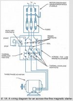
seems to me there should be. 3 hot in, 3 hot when switched out, 2 for starter switch. does the white wire from top left go to the magnetic starter switch?

explained here
 

Attachments

  • starter.JPG
    starter.JPG
    70.5 KB · Views: 6

Norcal

Well-known member
Joined
Mar 16, 2008
Messages
13,796
Unless it is part of a cable assembly like NM, MC, or a flexible cord, it is NOT permitted to re-identify a white to some other color, if it is in a conduit, it cannot be taped.
 
OP
T

tolken4

Well-known member
Joined
Nov 5, 2007
Messages
330
So, first thank you to everyone who gave input and guidance on this. I really truly love this forum.

Second, its alive!!!:shocking:

Third, It was a neutral because it was coming out the tail end of a 115v outlet box that had one leg of the three phase running in. What they had done was created a 115v circuit to power the magnetic relay on the starter and a convenience outlet attached to the lathe for whatever they needed I guess.

Lastly, this lathe came directly out of the picatinny arsenal and is wired as it was in the factory. I am confident in the wiring within the box. It was to code.

Three hots were running out to the L1-L2-L3 on the starter box. One leg was tied off of and headed up to an outlet box on top of the unit. From that box, a neutral was pigtailed into two other wires for a total of three.

1. from the outlet
2. to the starter
3. my missing link that just needed to be tied back to a neutral. I tied it back to a junction box where my single phase 40 amp was coming into to feed the Rotary Phase Converter. As that Neutral was not being used, this is kinda handy.

Thanks for the tip on the hot leg. I actually had it wired to L1 which is where the tap for the 115 was. Caught it in time.:thumbup:

If anyone sees anyway that I may be in danger of fire or explosion please speak now.
 
OP
T

tolken4

Well-known member
Joined
Nov 5, 2007
Messages
330
White wire should always be neutral unless recolored with phase tape.

Whatever u do, dont power single phase 120v loads from the generated leg and neutral. This is called the high leg or stinger leg and is 208v to neutral NOT 120v...

Thanks again for this Wylie. I had read about this and forgot to triple check it. You saved me some grief. Allthough I had planned on verifying the voltage coming out of that outlet box before powering up. Not sure what 208 would have done to the starter.
 
To avoid these ads, REGISTER NOW!
Top Bottom