To avoid these ads, REGISTER NOW!

Help wiring a reversible switch (drum switch?)

stinkity stoink

Well-known member
Joined
Apr 8, 2007
Messages
731
Location
New Jersey
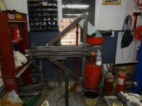
Hello all. I recently put a Dayton 1LRA6 gear motor on my bead roller. It is a 110 a.c motor that has forward and reverse.
I have it wired now for one way, but would like to be able to throw a switch and have it spin the other.
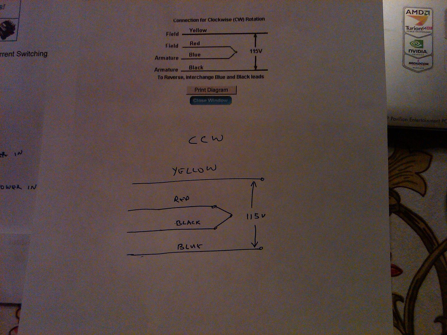
What I have is 4 wires c9 is black (line) , c1 is yellow (line), c7 is blue, c2 is red. To spin clock wise tie red and blue together. To spin counter clock wise I need to switch the blue and black wires.
I understand how it works and can get it to spin both ways . I just don't know how to wire it to a switch so that I flip it one way it's clock wise , flip the other and it's counter clock wise.
I am not sure if I need a drum switch or something else.

Thanks
 
To avoid these ads, REGISTER NOW!

lilredex

Well-known member
Joined
Apr 29, 2006
Messages
5,956
Location
Toronto
You can do that with a simple DPDT center off switch, something like these..

http://www.ebay.com/bhp/dpdt-center-off-switch

You need to run the start winding through there so the wires get reversed. Center off is needed as your motor probably has to come to a complete stop in order for the start winding to change the motor direction.

Check the switch operation with a powered test light to check the switch operation. Can provide specifics if you need them.
 

lilredex

Well-known member
Joined
Apr 29, 2006
Messages
5,956
Location
Toronto
Here is a typical diagram..


greenshot

Run your power (from the main on/off switch) to 2 and 5. Run your start windings to 1 and 4. Then run additional separate wires from 4 to 3 then another 1 to 6. The last step will reverse the juice to your start winding. The run winding also needs to be powered off your main on/off switch.
 
OP
S

stinkity stoink

Well-known member
Joined
Apr 8, 2007
Messages
731
Location
New Jersey
thanks for the quick responses ,but I am still not grasping this. Yellow (c1) is never changing. I assumed I could just wire that direct to my ac cord either hot or neutral. The rest confuses me . Sorry for the ignorance. I am not sure what is a start winding . Would that be red?
 

lilredex

Well-known member
Joined
Apr 29, 2006
Messages
5,956
Location
Toronto
The confusion is on my part...sorry. Without checking, I had assumed a resistance start type motor (with a start winding) but it's a universal type motor (with brushes).

http://www.grainger.com/Grainger/DAYTON-ACDC-Gearmotor-1LRA6

To switch those wires only, it is even simpler. You only need a SPDT switch (use half of that switch shown).

Put blue on 5, red on 4, and black on 6. Should do it and it will reverse instantly...no center off really needed. But there will be less stress on the motor if you do use the off position to stop before you change direction.

When you get the speed worked out, please post your results. I have a similar set-up to power with a similar gear motor. I had my wife time my simulated hand motion and I think we came up with a speed of 12-13 RPM.


how to take a screen shot

There is a guy on You tube with a HF drill belt driving a beader and he gets variable speed also.


EDIT....Being that is a universal type motor, you can use one of these types of controllers to vary the speed, but not as convenient as that drill arrangement.

http://www.harborfreight.com/router-speed-control-43060.html
 
Last edited:

Doug Arthurs

Well-known member
Joined
Dec 1, 2012
Messages
1,137
Location
Ontario
If you already have a drum switch then you shouldn't need to add an additional switch. This drum switch has a forward and reverse correct? I have my brideport mill running off one. My motor is 230v single phase but should work as well for 110v. Did the switch come with a wiring diagram?
 

laser3kw

Well-known member
Joined
Nov 17, 2012
Messages
7,276
Location
northen IL
You need to run the start winding through there so the wires get reversed. Center off is needed as your motor probably has to come to a complete stop in order for the start winding to change the motor direction.
important point
My lathe operates that way. Complete stop then switch or it continues to rotate in same direction.
 
OP
S

stinkity stoink

Well-known member
Joined
Apr 8, 2007
Messages
731
Location
New Jersey
I don't have a drum switch . I was not sure that is what I needed.

lilredx. thank you for the patients. I have never wired a switch like this.


If I tie the yellow to my neutral from my extension cord where does the hot go? I am not at all familiar with this switch.


I will post up the bead roller results soon. I just had surgery and am on quite a few pills for pain . Maybe that is what is making me so confused.
The motor was really simple to hook up. I used a piece of 1/8" plate bolted to the bead roller. Bolted the motor to the plate and connected them with a love joy coupling. I ran a few test beads an I thought the speed was great. It might be slow if doing long straight runs ,but I did not check on big pieces. When my shoulder is feeling better I am going to have to reinforce the bead roller.
 

lilredex

Well-known member
Joined
Apr 29, 2006
Messages
5,956
Location
Toronto
To spin counter clock wise I need to switch the blue and black wires.

Am confused again...what does this mean exactly?

Maybe it would be clearer if you could state (or better, a diagram) how the wires are connected for each direction. I had thought you meant, the above was blue and black tied together......not sure now.

Take your time and get better!
 

laser3kw

Well-known member
Joined
Nov 17, 2012
Messages
7,276
Location
northen IL
yellow stays constant to line either forward or reverse?
tie black and blue together and line to red = reverse?
red and blue tied together and black to line = forward?
 
To avoid these ads, REGISTER NOW!
OP
S

stinkity stoink

Well-known member
Joined
Apr 8, 2007
Messages
731
Location
New Jersey
I have that much down. I am trying to figure out how to run it through a switch. This way I just flip the switch to reverse the motor. I don't want to have to pull the wires apart to make it reverse. Thanks
 

laser3kw

Well-known member
Joined
Nov 17, 2012
Messages
7,276
Location
northen IL
yellow stays constant to line either forward or reverse?
tie black and blue together and line to red = reverse?
red and blue tied together and black to line = forward?

(anyone remember Boolean logic)

If the above is true then:

DPDT switch

red (1) l......l (4) black (switch "up" - forward)

blue (2) l......l (5) line (switch common)

black (3) l......l (6) red ( switch "down" - reverse)


yellow ---> striaght thru to motor

with switch up / forward - blue / red tied and line goes to black
with switch down / reverse - blue and black tied and line goes to red
 
Last edited:
OP
S

stinkity stoink

Well-known member
Joined
Apr 8, 2007
Messages
731
Location
New Jersey
(anyone remember Boolean logic)

If the above is true then:

DPDT switch

red (1) l......l (4) black (switch "up" - forward)

blue (2) l......l (5) line (switch common)

black (3) l......l (6) red ( switch "down" - reverse)


yellow ---> striaght thru to motor

with switch up / forward - blue / red tied and line goes to black
with switch down / reverse - blue and black tied and line goes to red

That was the ticket. Thank you !
Once I got off the pain pills and was able to do a little work it clicked. I appreciate the help.
Thanks
 

laser3kw

Well-known member
Joined
Nov 17, 2012
Messages
7,276
Location
northen IL
Once I got off the pain pills and was able to do a little work it clicked.
Glad you are feeling better and got your project to work. I was starting to wonder what happened.
ps - pain pills and electricity don't mix :lol:
 
OP
S

stinkity stoink

Well-known member
Joined
Apr 8, 2007
Messages
731
Location
New Jersey
oops here they are. It beads 18 gauge in a single pass easily. It moves about 30" per minute. I use a harbor freight electric foot pedal to control it to stop or just do a small bead.
I have only fooled around with it so far ,but it seems to work real well
 

Attachments

  • DSC00941.JPG
    DSC00941.JPG
    137.2 KB · Views: 51
  • DSC00940.jpg
    DSC00940.jpg
    42.9 KB · Views: 49
  • DSC00939.JPG
    DSC00939.JPG
    144.6 KB · Views: 54
  • DSC00938.jpg
    DSC00938.jpg
    41.4 KB · Views: 47

37ford4dr

Well-known member
Joined
Jan 5, 2012
Messages
109
Location
Arlington Va
HELP....

i am doing the same set up almost exactly .....purely by coincidence but i am using a drum switch.

i kind of understand what i need to do but what i dont understand is the red/blue wire always tied together?

dayton ac/dc gear motor

yellow is field and that looks like it always has power to it

red is field and its tied to blue armature.

black is armature

so powering yellow and black make the motor spin one way

and it says to reverse motor direction change blue and black

does that mean yellow and red tied to blue make it spin the other way?

is the red always tied to the blue?

thks bob

IMG03329-20140110-1637_zpsff50629b.jpg


IMG03328-20140110-1621_zpsbf4c22d3.jpg


IMG03331-20140110-1740_zps6e737dcb.jpg


IMG03335-20140110-1909_zpsf5e73616.jpg
 
Last edited:

laser3kw

Well-known member
Joined
Nov 17, 2012
Messages
7,276
Location
northen IL
I am thinking it means:
dpdt switch

blue(1) l......l (4) black (switch "up" - forward)

red (2) l......l (5) line (switch common)

black (3) l......l (6) blue ( switch "down" - reverse)

forward = red & blue tied / line to black as shown on label
reverse = red & black tied / line to blue
yellow >>>> line
it maintains line on field and line on arm
Now here is the caveat: do this at your own risk. consult Dayton to be sure. Grainger may be able to help also.
 

37ford4dr

Well-known member
Joined
Jan 5, 2012
Messages
109
Location
Arlington Va
EDIT I have wired it up this way and it works!!!! the motor goes forward and reverse.

thks laser3kw i have a different reversing switch but putting the red in the middle is key.....


i have been staring at this long enough that i think i figured it out .....can someone please confirm i have this right, thks bob

heres the motor wiring diagram

IMG03336-20140110-2146_zps1772d49e.jpg


heres the drum switch wiring diagram with my colored wires noted next to it

IMG03337-20140110-2146_zps2dcd2a51.jpg
 
Last edited:
To avoid these ads, REGISTER NOW!
Top Bottom