freudianfloyd
Well-known member
I need help from those who are smarter than me but can dumb this down to a first graders level. I used to be able to do way more complicated things than this, but I honestly think I am losing it.
I am trying to hook up a drop bolt lock on my office/gun room door so the little ones can't easily get in, and so I don't have to carry a key with me to lock it everytime I enter.
I have the power supply hooked up in the basement, I also have the wires running up into the wall and the key pad and exit button boxes installed. I have also installed the drop bolt solenoids into the door frame. The last thing I need to do is connect it all together, but for some reason it just isn't as clear as I hoped it would be. I don't currently have a battery back up and want it wired so the drop bolts release if the power goes out, that way I can't get locked in my office.
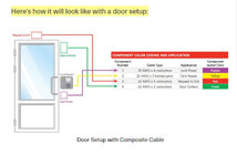
This is the equipment I have, and the wiring diagrams for each. Can somebody please break it down for me on exactly which wire connects to where?
Power Supply

Keypad


Solenoid


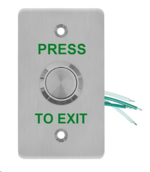
Exit Button

Now I know to some of you this is easy, but for some reason, none of the diagrams show how to hook this up exactly like I need to, and I am just getting more and more frustrated.
Any help would be greatly appreciated.
I am trying to hook up a drop bolt lock on my office/gun room door so the little ones can't easily get in, and so I don't have to carry a key with me to lock it everytime I enter.
I have the power supply hooked up in the basement, I also have the wires running up into the wall and the key pad and exit button boxes installed. I have also installed the drop bolt solenoids into the door frame. The last thing I need to do is connect it all together, but for some reason it just isn't as clear as I hoped it would be. I don't currently have a battery back up and want it wired so the drop bolts release if the power goes out, that way I can't get locked in my office.
This is the equipment I have, and the wiring diagrams for each. Can somebody please break it down for me on exactly which wire connects to where?
Power Supply
Keypad
Solenoid
Exit Button
Now I know to some of you this is easy, but for some reason, none of the diagrams show how to hook this up exactly like I need to, and I am just getting more and more frustrated.
Any help would be greatly appreciated.