To avoid these ads, REGISTER NOW!

Help wiring lathe

Joined
May 21, 2008
Messages
22
Location
D.F.
Hello all,

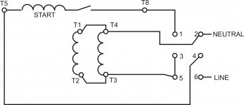
I recently got a new to me lathe. I need to wire the motor to the drum switch. I think I have the switch figured out but my motors wires don't match the motor label. Hopefully you can help.

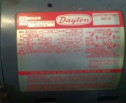
It's a .5 HP Dayton motor. Being wired for 115V.

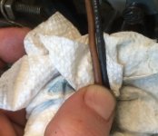
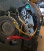
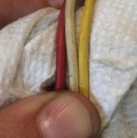
As you can see in the pictures, the label calls for Brown, red, black, and white.

I also have yellow. I'm thinking that the yellow is just a ground and it goes to the shiny bolt inside the wire box? If so, would you also connect it to the ground inside the drumswitch, and eventually to your 3rd prong on the plug?

Figured I'd ask before just winging it.

Thanks in advance
 

Attachments

  • FullSizeRender_1.jpg
    FullSizeRender_1.jpg
    120 KB · Views: 46
  • FullSizeRender_2.jpg
    FullSizeRender_2.jpg
    129.1 KB · Views: 71
  • FullSizeRender_3.jpg
    FullSizeRender_3.jpg
    113.3 KB · Views: 73
  • FullSizeRender.jpg
    FullSizeRender.jpg
    107.3 KB · Views: 38
To avoid these ads, REGISTER NOW!

RPH

Well-known member
Joined
Dec 17, 2006
Messages
4,190
Location
Michigan Thumb
Is the motor reversible? One of the functions of drum switch is to reverse the motor as well as stop. And the ground never gets switched. Better pic of motor label would help.
 

LXCam

ALLIANCE MEMBER
Joined
Apr 23, 2013
Messages
19,106
Location
AZ
Not real sure about that assumption. If you have a ohm meter check continuity between the yellow and all the other leads. If it is a ground, there should not be any continuity. If there is determine which leads tie together (coil leads) and report back.
 
OP
E
Joined
May 21, 2008
Messages
22
Location
D.F.
I tried google. Didn't find much. I find diagrams that state the same as the label. No explanation for the extra yellow wire.

Yellow has NO continuity to any of the other wires or the frame. However, it DOES have continuity to terminal 3 (the upper most one). According to the label, brown should hook up to terminal 3.

The black wire is one of the two that come out of the capacitor. In case it helps.

Here is another shot of the label.

Thanks
 

Attachments

  • image.jpg
    image.jpg
    142.4 KB · Views: 51

LXCam

ALLIANCE MEMBER
Joined
Apr 23, 2013
Messages
19,106
Location
AZ
Call the grainger help line tomorrow. They have access to anything and everything about Dayton motors. Sound to me like the yellow lead ties to one of the other posts but the terminal got cut off for some reason. I'd also suggest referencing an ugly booklet for typical wiring diagrams. If I can make out into the shop and find mine I'll get back to ya.
 

6PTsocket

Well-known member
Joined
Mar 12, 2014
Messages
4,593
I suspect it might have something to do with the start circuit that is not part of the wiring that gets rewired for fwd or reverse or for selecting 120 or 220. The start circuit consists of the start winding, the start capacitor and the centrifugal switch, all wired in series, across the AC line. One side of the start winding is internally tied to one side of the run winding and goes to one side of the AC line. The capacitor and centrifugal are in series and it does not matter in what order. The wire may be coming from the centrifugal switch and depending how the motor is wired, might go to the other side of the AC line. This is where an ohm meter comes in, to see what is going where. It is not a ground, which is green, when present.

Sent from my SM-G900V using Tapatalk
 

MushCreek

Well-known member
Joined
Jan 14, 2015
Messages
9,763
Location
Upstate South Carolina
Bear in mind that if it's an ordinary single phase motor, it won't instant reverse. If you reverse the switch quickly, it will keep going in the same direction. Gets interesting when you're power tapping.... You have to let it come to a stop before reversing.
 

1953mercury

Well-known member
Joined
Nov 25, 2012
Messages
701
Location
Steamboat Springs CO
Any reason your not using the 230V option? More power/less draw that way. Sorry can't help with the wiring, but the Grainger option is a good idea. Mike
 

rockwithjason

Well-known member
Joined
Jan 8, 2006
Messages
2,633
Location
Las Vegas
wire it up like the plate shows and insulate the yellow wire, then test run. if the motor runs in both directions then cap the yellow wire and forget about it. the ground connects to the case via the green screw in the upper section of the picture.
 

DenisG

Well-known member
Joined
Jul 14, 2013
Messages
1,278
Location
Milwaukee
Maybe this helps:

"The National Electrical Manufacturers Association (NEMA) has color coded the terminal leads. If colors are used, they should be coded as follows: T1 — blue; T2 — white; T3 — orange; T4 — yellow; T5 — black; and T6— red."

Source: http://www.industrial-electronics.com/elecy4_22.html
 

Attachments

  • elec4_22-8.jpg
    elec4_22-8.jpg
    34.8 KB · Views: 30

6PTsocket

Well-known member
Joined
Mar 12, 2014
Messages
4,593
Bear in mind that if it's an ordinary single phase motor, it won't instant reverse. If you reverse the switch quickly, it will keep going in the same direction. Gets interesting when you're power tapping.... You have to let it come to a stop before reversing.
His problem is more fundamental than how long it takes to reverse. He has an unidentified wire and unless the motor is properly wired it will not run in any direction or may burn up. Getting it correctly wired comes first.

Sent from my SM-G900V using Tapatalk
 

6PTsocket

Well-known member
Joined
Mar 12, 2014
Messages
4,593
wire it up like the plate shows and insulate the yellow wire, then test run. if the motor runs in both directions then cap the yellow wire and forget about it. the ground connects to the case via the green screw in the upper section of the picture.
I have wired many motors on the job, and all the wires go somewhere. The fact that it is not on the plate suggests that is a connection that does not select voltage or direction but may go to something like the centrifugal switch. Plug in and try is not how you figure out how to wire something. It is a great way to smoke something. If he follows your advice and smokes the motor, are you going to replace it?

Sent from my SM-G900V using Tapatalk
 

6PTsocket

Well-known member
Joined
Mar 12, 2014
Messages
4,593
You copied a drawing that only shows half of his circuit. Go down further and look at capacitor start motors with a centrifigal switch. There is no drawing there that shows 120/220 reversing and capacitor start. He said that he had a start capacitor and it is not showed in your drawing. He has 5 wires, not 8. His plate covers all wires for 120/220 and reversing. You have to go beyond color code He does not have the wires to duplicate what you are showing. If he is not knowledgeable enough to trace the circuit, he should find someone who is and not rely on guesses.

Sent from my SM-G900V using Tapatalk
 
To avoid these ads, REGISTER NOW!

rockwithjason

Well-known member
Joined
Jan 8, 2006
Messages
2,633
Location
Las Vegas
I have wired many motors on the job, and all the wires go somewhere. The fact that it is not on the plate suggests that is a connection that does not select voltage or direction but may go to something like the centrifugal switch. Plug in and try is not how you figure out how to wire something. It is a great way to smoke something. If he follows your advice and smokes the motor, are you going to replace it?

Sent from my SM-G900V using Tapatalk

no sargent wise guy, I will not replace it. this dude came here looking for suggestions. the suggestion I gave is the one I would use myself. after 21 years in the trade I have enough confidence in my answer to put it up here. maybe he takes it, maybe he doesn't. no skin off of my back either way. there is always one guy like this on a thread, this time its you.
 

matt_i

Well-known member
Joined
Mar 14, 2008
Messages
10,725
Location
SE Michigan
If you had 2 yellow wires I'd say a thermal overload switch. i like the idea of tech support if time is available for that call but in a time crunch I'd roll like Rockin Jason.
 

ard

Well-known member
Joined
Feb 16, 2015
Messages
4,391
Location
Sierra Foothills... California

I thought so, hence my advice on googling... ;)

FYI, if you place a square bracket, [, then an IMG, then close the bracket with ]...then instert the link, then finish with [ then /img then] you get:

2014-08-06_102318_dayton_motor_and_4uye9_drum.jpg
 

manwithtools

ALLIANCE MEMBER
Joined
Aug 24, 2015
Messages
13,730
Location
Lebanon, TN
I have wired many motors on the job, and all the wires go somewhere. The fact that it is not on the plate suggests that is a connection that does not select voltage or direction but may go to something like the centrifugal switch. Plug in and try is not how you figure out how to wire something. It is a great way to smoke something. If he follows your advice and smokes the motor, are you going to replace it?

Sent from my SM-G900V using Tapatalk

Then you need to wire some more motors on the job....

There are multiple instances of unused leads in motors depending on the motor and application. Universal HVAC replacement motors come to mind right away. Multi-voltage (more thane 2) motors may result in the same.
 

DenisG

Well-known member
Joined
Jul 14, 2013
Messages
1,278
Location
Milwaukee
You copied a drawing that only shows half of his circuit. Go down further and look at capacitor start motors with a centrifigal switch. There is no drawing there that shows 120/220 reversing and capacitor start. He said that he had a start capacitor and it is not showed in your drawing. He has 5 wires, not 8. His plate covers all wires for 120/220 and reversing. You have to go beyond color code He does not have the wires to duplicate what you are showing. If he is not knowledgeable enough to trace the circuit, he should find someone who is and not rely on guesses.

Sent from my SM-G900V using Tapatalk

He said that the yellow wire has continuity with T3. That makes the yellow T4. The information that I provided shows why. T1 thru T4 are connected to the run windings. T5 thru T8 are connected to the start windings. All the colors and all the wires are not always visible until you remove the terminal block. If you like to test things at random, that's your choice. I like things to make sense.
 

6PTsocket

Well-known member
Joined
Mar 12, 2014
Messages
4,593
Then you need to wire some more motors on the job....

There are multiple instances of unused leads in motors depending on the motor and application. Universal HVAC replacement motors come to mind right away. Multi-voltage (more thane 2) motors may result in the same.
This is not some multi speed HVAC motor. It is a 120/220 reversable. The two run windings are in series or parallel and the start winding is in series with the capacitor and the centrifugal switch, across the AC line. That is what I was referring to. Not split phase, not with a run capacitor, not three phase, or any of the irrelivant variations you can come up with. No place I ever worked was anybody so irrisponsible to guess where the wires went and plug it in to see what would happen.

Sent from my SM-G900V using Tapatalk
 

6PTsocket

Well-known member
Joined
Mar 12, 2014
Messages
4,593
no sargent wise guy, I will not replace it. this dude came here looking for suggestions. the suggestion I gave is the one I would use myself. after 21 years in the trade I have enough confidence in my answer to put it up here. maybe he takes it, maybe he doesn't. no skin off of my back either way. there is always one guy like this on a thread, this time its you.
Getting nasty will just get this thread closed. If you think name calling adds to the conversation, it sort of looks like you are the one on this thread. I just pointed out that the circuit you posted does not show the capacitor start circuit. He said his motor has a capacitor. Some of the drawings further down the page are capacitor start. That part of the wiring is not usually shown on the plate. This is supposed to be a discussion, not an argument.

Sent from my SM-G900V using Tapatalk
 

manwithtools

ALLIANCE MEMBER
Joined
Aug 24, 2015
Messages
13,730
Location
Lebanon, TN
This is not some multi speed HVAC motor. It is a 120/220 reversable. The two run windings are in series or parallel and the start winding is in series with the capacitor and the centrifugal switch, across the AC line. That is what I was referring to. Not split phase, not with a run capacitor, not three phase, or any of the irrelivant variations you can come up with. No place I ever worked was anybody so irrisponsible to guess where the wires went and plug it in to see what would happen.

Sent from my SM-G900V using Tapatalk

I never said this motor had unused wires nor did I suggest someone guess at the connections. Simply pointing out the fact that just because you personally have not encountered motors with unused wires does not mean they don't exist.

I was alerting others that might read this thread in the future that motors with unused wires can be encountered.

OP, have you contacted Dayton yet for clarification?
 

6PTsocket

Well-known member
Joined
Mar 12, 2014
Messages
4,593
That last drawing is almost the right one.
The start capacitor, when there is one is in series with the start winding and the centrifugal switch In this drawing it would be between terminals T5 and 4, though the order of parts in a series circuit doesn't matter. Between the switch and the coil or in place of the jumper between T8 and 1 would work too. T5 and 4 is the most likely. The switch and the cap are usually on opposite sides of the coil

Sent from my SM-G900V using Tapatalk
 

DenisG

Well-known member
Joined
Jul 14, 2013
Messages
1,278
Location
Milwaukee
That last drawing is almost the right one.
The start capacitor, when there is one is in series with the start winding and the centrifugal switch In this drawing it would be between terminals T5 and 4, though the order of parts in a series circuit doesn't matter. Between the switch and the coil or in place of the jumper between T8 and 1 would work too. T5 and 4 is the most likely. The switch and the cap are usually on opposite sides of the coil

Sent from my SM-G900V using Tapatalk

Check again. If the centrifugal switch is between T4 and T5, what happens when it closes?
(And the fact that the centrifugal switch is a NC switch is moot.)
 
Last edited:

6PTsocket

Well-known member
Joined
Mar 12, 2014
Messages
4,593
Check again. If the centrifugal switch is between T4 and T5, what happens when it closes?
(And the fact that the centrifugal switch is a NC switch is moot.)
Please read what I wrote again. I did not say between T4 and T5. I said 4 (no T) and T5. All three components are in series. It is not that complicated. Also, the capacitor is for AC and has no polarity so the leads to the capacitor are interchangable.

Sent from my SM-G900V using Tapatalk
 
To avoid these ads, REGISTER NOW!
Top Bottom