I know this thread of mine is very old, but there were never any definitive answers on the neutral situation, and it has caused much confusion.
I still have not wired this in lol, and am looking into it again as I want to get it completed.
I have asked a few electricians over the past few years about the neutral question and all had very confused looks on their faces and weren't sure of what to say.
No disrespect intended towards my electrician friends... but it's not really a question that they would be able to answer unless they have a lot of experience with power systems design. You need to be talking to an engineer, specifically one with power generation/distribution experience. That's likely why you haven't received a 'straight answer' from anyone on this subject... what you want to do it not an easy thing to whip out in a few minutes. It's going to take some work.
Although they all said they've done plenty of single panel generator input boxes, and never did anything with checking a G/N bond on the generator itself, nor have ran a portable generator ground to the grounding rod, as was mentioned in this thread, saying that the the G/N is already together in the panel, and the panel is already grounded to the rod, making no difference if the generator is bonded to itself or grounded to the rod either way.
Right... because they don't typically have their heads buried in the National Electrical Code (NEC) and know where to look for it. They may not understand the difference between a system that has a
Separately Derived Source or not.
If you are using a generator out in the field for a party and you aren't tied into any distribution equipment, then the safe and proper thing to do is to drop a ground rod and tie the generator to it. The generator will be the only source, so it will have the neutral/ground bond established inside of itself. No problems.
But if your intent is to tie that generator into an existing system like a house panel, then you have to decide how to do it, and do it correctly. If you want to have a non-separately derived system, then remove the system bonding jumper (neutral/ground bond) at the generator. Run four conductors from the generator to the panel. (L1, L2, Neutral, and ground.) The only neutral/ground bond will be at the panel. You can drive another ground rod for the generator if you want, just make sure to tie all of the grounds together so it's basically one big grounding system.
If you don't remove the neutral/ground bond at the generator, then you HAVE to have a way to switch the neutral between two sources. That typically means having a 3-pole switch for a typical single phase 240 VAC system, or a 4-pole switch for a 3-phase 208 VAC and/or 480 VAC system. But the fact is... you don't have a way to 'lift' the neutral from the POCO in your panel and remove the neutral/ground inside the panel. Even if you could, you likely wouldn't want to do that... so you need to step back and think about a better approach.
Are these electricians hacks? Are they doing it wrong? I don't know, but I'd still love to find out. So I can wire my dual panels properly and safely.
I have no idea if they are hacks or not... and it's not for me to judge based on the limited info given. But as I said, your question is more about how to properly design the system so that it meets your needs and is correct per the NEC. That's not typically a job for an electrician... that's a job for an engineer. (Again, no disrespect intended towards electricians. I've known some master electricians that can run circles around engineers all day long. Not every electrician is an idiot, and engineers don't know everything because of a college degree.)
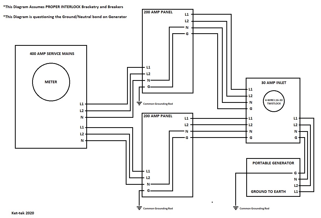
Here are some diagrams I made to show the 3 scenarios I interpreted from this thread, I would love to get any feedback from the experienced guys here that have been willing to discuss this in the past.
This shows as previously discussed how some generators have the Ground and Neutral Bonded which would also be connected to the Frame from what I understood, which is supposedly bad?
 dual panel bonded
 by
...
This one shows a generator with no bond or the bond removed.
 dual panel unbonded
 by
...
And this one with no bond and the generator grounded to the panel ground rod.
 dual panel grounded
 by
...
None of those drawings are correct, because none of them show a neutral/ground bond in the panels. In all three drawings, you are trying to backfeed two panels with one generator... and each panel is really considered it's own 'source' because that's where the neutral/ground bond is established in each panel. Technically, you are only allowed one.
If you want to figure this out on your own, I would suggest getting a copy of the NEC. Look in Section
250.30 Grounding Separately Derived Alternating-Current Systems. It explains the difference between a Separately Derived System and a Non-Separately Derived System.
Non Separately Derived System:
Separately Derived System:
For a system that is not separately derived, there is no system bonding jumper inside the generator. (Neutral/Ground Bond.) The neutral and the equipment grounding conductor (or supply side bonding jumper) are separate conductors that go back to the transfer switch. The neutral and the ground stay separated in the transfer switch and stay that way all the way back to the main panel, where the neutral/ground bond takes place.
If you had a Separately Derived System, then you would look at each source as being it's own, independent source. Each would have it's own system bonding jumper (neutral/ground bond) at the source, and the transfer switch would be a 3-pole (single phase) or 4-pole (three-phase) unit that automatically swaps the neutral from one source to the other. That way you don't have the possibility of any circulating currents from one source to the next.
The problem as I see it, is that in your examples above the POCO is supplying power to your panels, but because the meter does NOT have a neutral/ground bond then each panel is considered the 'source' of power to each structure. Each panel has it's own established neutral/ground bond. So if you try and feed both panels from one generator, how do you keep the neutrals and grounds separated? What happens when one panel is fed from the E/G and other other is fed by commercial power? Aren't the neutrals and grounds connected together in the generator 30A plug? If so... you have a problem.
The best way to power both panels is to get yourself a Service Entrance rated 400A Automatic Transfer Switch (ATS) and put it between the meter and the two panels as shown above. The transfer switch would establish the neutral/ground bond for the system, and the two 200A panels would become sub-panels. You would need to separate the neutrals and the grounds in each panel, likely add a ground bar in each panel, and remove the system bonding jumpers (neutral/ground bond) in each panel. (A Kohler 400A Automatic Transfer Switch is about $2,800) Do a proper load study and size the generator to the loads. (Or drop in a 80kW/100kVA to 'match' the 400A service... but I'd bet that it's serious overkill.)
As it was pointed out before, it doesn't matter how many panels you feed from the generator... provided the generator has the power to supply all of the loads. If it's not big enough, then you have to have a way to shed the loads that are not needed/required when the generator is on-line. Some ATS's have automatic load shed capabilities, some do not. If you are doing it manually, then technically you would need to split each panel into two panels: Essential and non-Essential loads. Essential loads would be powered by the E/G, non-essential loads would not. The generator would have to be rated to handle all of the Essential loads... and you're looking at some big $$$ to try and split the loads into what would become four panels in this instance.
Hope this helps.
Mark


