To avoid these ads, REGISTER NOW!

Help with acme threaded rod!

NC_AC

Member
Joined
Jun 15, 2022
Messages
7
Location
North Carolina
Hey folks! I'm working on a tool restoration and it came with a shop made table lift that revolves (no pun intended) around a length of acme threaded rod. Long story shot, the rod doesn't allow the table to go high enough for my liking, so I'm trying to replace the rod with a longer piece, but struggling to ID the exact specs needed.

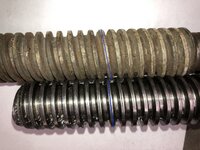
I just ordered/received a length of 1 1/4"-4 'acme lead screw' from McMaster Carr (part 98935A112) that I was certain would work - nope. It seems like the correct thread size, but the angle of the threads is wrong so it won't fit the threaded lift component I'm working around - that's where I'm stumped. Attaching a photo below.

I'm a total newb when it comes to this kind of stuff, so I suppose it's not a huge surprise that I got this wrong, but certainly a bit frustrating. Not sure if this part is available elsewhere, and not sure what dimension/spec I missed.

Any help would be super appreciated!

Adam
 

Attachments

  • IMG_4862.JPG
    IMG_4862.JPG
    311 KB · Views: 116
To avoid these ads, REGISTER NOW!

RoninB4

Well-known member
Joined
Jul 22, 2020
Messages
3,621
Location
Under My House
To start with, did you lay one threaded rod against the other as a quick check of number of threads per inch? They'll need to be able to "lay inside" each other, close is not close enough. Working from my poor memory there are several types of Acme threads, including "modified Acme". Only way to be sure is checking the profile under magnification on a shadow graph (expensive optical comparitor), using an Acme thread gauge (not very expensive), or making a new nut and tapping it (not very expensive). I don't know what you have available, your skill level, or whether replacing the nut is even possible. Acme threads come in several different flavors with different angles and geometry.

You didn't screw up, it's not a simple thing to replace them without knowing exactly what you have. I have 45 years of tooling/machinery and I'd have to purchase an Acme thread gauge too. At this point you've already paid for the new lead screw, the existing nut may very well be a bit worn and replacing a worn nut on a lifting device might not be a bad idea anyway. I've seen elevation nuts on huge radial arm drills fail due to wear and it was fortunate nobody was injured when it just let loose.

What do you want to do? Check the TPI (threads per inch) first.


Update- used the image you supplied and did a quick check in Paint. The TPI appears to be off 1/2 thread in 6 revolutions. Granted this isn't a good way to check things but laying them together should readily show if it's off. Laying them both on white paper or with a light source in the background helps. Is it possible that the original is metric? If you have a decent set of calipers it should be easy to determine over 1" or more whether the TPI is correct or not. Hope this helped.
 
Last edited:

mike93lx

ALLIANCE MEMBER
Joined
Dec 9, 2013
Messages
37,949
Location
Richmond, VA
Try this


nadogail

Well-known member
Joined
Jan 23, 2009
Messages
32,057
Location
Coronado, CA
Google search BALL SCREWS AND ACTUATORS. I used them when I was doing maintenance for a plant making printed wiring boards.

I was buying repair parts for machines from the makers of the parts, avoiding the markedup prices from the company that built and sold the machine.
 

sz0k30

Well-known member
Joined
Feb 12, 2014
Messages
887
Location
SE Michigan
Lay a ruler on the new piece you bought. Measure how many threads you have in one inch. Since you bought 1-1/4-4, it had better be 4. Now measure your old piece the same way and count how many threads in 1". Then measure the diameter.
 
OP
N

NC_AC

Member
Joined
Jun 15, 2022
Messages
7
Location
North Carolina
I can confirm they're both the same thread size (as far as I can see) - but the angle of approach of the threads is different. You can see the threads don't fit inside each other perfectly, although they do line up. Seems like it's due to the steepness of the threads - not sure what that spec is called exactly.

I don't think this is a ball screw because the threads are trapezoidal and not round for a ball bearing, etc.

I do not have any machining tools and need to match the original rod because the lifting mechanism is threaded for that exact type rod - again I can't manufacture anything like that in my small wood shop so I'd rather match the existing than get down that path. Is there any other method to identifying this exact type of acme thread?

I appreciate all the help so far!
 

Attachments

  • IMG_4864.JPG
    IMG_4864.JPG
    339.4 KB · Views: 88
  • IMG_4865.JPG
    IMG_4865.JPG
    307 KB · Views: 78
  • IMG_4867.JPG
    IMG_4867.JPG
    371.4 KB · Views: 83

PelicanPines

ALLIANCE MEMBER
Joined
Apr 30, 2014
Messages
38,144
Location
New Jersey, USA, Earth, My own reality
I believe “lead”, pronounced leed, is your problem. It sounds like one of your shafts has one thread around and around, and the other shaft may have as many as four threads intertwined, known as twin-lead, three-lead, or four-lead.
I think. It’s been thirty years since machine shop class.
^^^^ ---- this.
 

larry_g

Well-known member
Joined
Apr 28, 2007
Messages
16,899
Location
oregon
If I may make a couple of suggestions;

The above talk about leads of multiple starts. Three ways to check this

1. look at the end of the shafts. A single lead will have one thread start and wind up the shaft. A multiple lead will show two or more starts.

2. Measure how far the old shaft moves per turn A 4 pitch should move 1/4" per turn. I'd suggest that you measure how far it moves in 8 turns. If it moves 2 inches then it's 4 pitch. If it moves something different than 2" in 8 turns then you have a some other pitch or multiple starts.

3. Using your finger on the peak if the thread, follow it around the shaft 360* and it should come out on the peak of the thread next to where you started. If it skips a peak then it is multi start.


lg
no neat sig line
 
OP
N

NC_AC

Member
Joined
Jun 15, 2022
Messages
7
Location
North Carolina
I believe “lead”, pronounced leed, is your problem. It sounds like one of your shafts has one thread around and around, and the other shaft may have as many as four threads intertwined, known as twin-lead, three-lead, or four-lead.
I think. It’s been thirty years since machine shop class.

Spot on - I had no idea such a thing existed. Like I said, total newb here. Thanks also to @larry_g - I checked the bottom of the old shaft and sure enough, found two starts. To be sure, I traced a thread and it skips a thread as I go around. Kinda hard to see in the attached photos, as each thread starts on the opposite side. Thanks for the assist, folks! So great to be able to find knowledgable help on a fairly obscure topic.

(Note: the reason the bottom of the shaft pictured below has been ground down is that this end of the rod sits in a flange bearing mounted on the base of the drill press.

So it sounds like I'm looking for a 1 1/4" - 4 twin-lead rod, correct me if I'm wrong! Any idea what my next step would be to procure said shaft? I googled and didn't immediately see options, nor does McMaster Carr seem to carry anything beyond the single thread that I can tell. Or is this something a machine shop could fabricate?
 

Attachments

  • IMG_4869.JPG
    IMG_4869.JPG
    246.5 KB · Views: 71
  • IMG_4868.JPG
    IMG_4868.JPG
    226.7 KB · Views: 71

paulsomlo

Well-known member
Joined
Jul 16, 2013
Messages
3,913
Location
Northern Colorado
So it sounds like I'm looking for a 1 1/4" - 4 twin-lead rod, correct me if I'm wrong! Any idea what my next step would be to procure said shaft? I googled and didn't immediately see options, nor does McMaster Carr seem to carry anything beyond the single thread that I can tell. Or is this something a machine shop could fabricate?
Sure - $$$

The suggestion above makes more sense - if you can stand to lose some range at the bottom of travel, add an unthreaded section at the thrust bearing end; could be welded then turned concentric, or drill the thrust bearing end, turn down a plain shaft for a slip fit, and pin them.
 

whateg01

Well-known member
Joined
Mar 13, 2006
Messages
11,542
Location
doo dah, kansas, usa
That's an odd size, it seems. McMaster does have multi start screws but not in that size. They jump from 1" to 1.5".

Aside from modifying the existing screw, you might have to have one made. Or modify the bench to use a more common screw size. I've got a similar situation where I need a 7/8-8 LH nut. Fortunately, I have the tools and the ability to turn a new one.

Sounds like you'll have to decide how badly you want to modify your bench
 
To avoid these ads, REGISTER NOW!
OP
N

NC_AC

Member
Joined
Jun 15, 2022
Messages
7
Location
North Carolina
Can you weld and extension to lift the bench?

Do you mean extend the bottom of the shaft that fits into the flange bearing component? That would work - although I don't have any equipment or ability to weld. But in theory I'm fine with not having threads for the bottom portion of the shaft, I don't foresee ever needing the drill press table to go that low on the column.

If I don't have the abilities personally, would this be a job for a welding shop or a machine shop or...any thoughts on best direction to source help?
 

RoninB4

Well-known member
Joined
Jul 22, 2020
Messages
3,621
Location
Under My House
Good catch by TurnipTruck with an assist from Larry_G. The possibility of multi lead feed screws slipped my mind. Never liked using multi leads except for higher end machinery where (relatively) rapid movement and high thrust loads required it.

To the OP- If you're having trouble sourcing this lead screw are you sure the nut (female part) can't be replaced to match the screw you already have. Yes you can contact a machine shop to make a double lead but it will be comparatively expensive and if they don't have the part (nut) it threads into it still might not fit well. The more common type you just bought will be slower in raising the platform but it will be much less expensive and easier to source a tap to match the new screw. I realize you have limited metal working machinery but perhaps cutting out the old nut, fabricating a new one, and installing the new nut could be cheaper/easier for a machine shop to do. Can you take some photos of the nut area? Perhaps another idea will come to mind.
 
Last edited:

woodscaper

Well-known member
Joined
Aug 18, 2013
Messages
105
Location
central pa
Yup, double lead thread, used a lot in large valves for faster actuation. Had double and triple lead too where I used to work building nuclear power plant valves.
 
OP
N

NC_AC

Member
Joined
Jun 15, 2022
Messages
7
Location
North Carolina
To the OP- If you're having trouble sourcing this lead screw are you sure the nut (female part) can't be replaced to match the screw you already have. Yes you can contact a machine shop to make a double lead but it will be comparatively expensive and if they don't have the part (nut) it threads into it still might not fit well. The more common type you just bought will be slower in raising the platform but it will be much less expensive and easier to source a tap to match the new screw. I realize you have limited metal working machinery but perhaps cutting out the old nut, fabricating a new one, and installing the new nut could be cheaper/easier for a machine shop to do. Can you take some photos of the nut area? Perhaps another idea will come to mind.

For sure - attached is a picture of the pre-restoration drill press and table raising mechanism. You can see the bottom of the current shaft fits into a flange bearing mounted to the drill press base - which goes up to a set of beveled gears and a crank. Then the actual 'arm' portion fits around the table clamp - and that's what you're getting at I believe. The 'nut' portion is a block of aluminum threaded for the existing rod which is then attached to a welded bit of steel fitting around the column and the table mount.

IMO, whoever designed the mechanism had a good idea as it's very solid with smooth action - albeit not the most pretty thing ever. I only really need to extend the rod another 8 inches or so.

Seems like my options are: a) get someone to weld an extension to the bottom of the existing shaft (which is totally fine, I'll never need the table down at the bottom of the column) or b) have a machine shop fabricate a new 'nut' with the more standard single start acme rod I bought already - then attach the new nut/block to the arm piece the same way the original does.

Any other options from you smart folks?
 

Attachments

  • IMG_4660.JPG
    IMG_4660.JPG
    345.5 KB · Views: 63
  • Screen Shot 2022-07-21 at 3.59.49 PM.png
    Screen Shot 2022-07-21 at 3.59.49 PM.png
    1.3 MB · Views: 70

RoninB4

Well-known member
Joined
Jul 22, 2020
Messages
3,621
Location
Under My House
Any other options from you smart folks?
Well I can't be accused of being smart but do have a suggestion. Since you said you won't be needing the table that low (having said that you will some day) you needn't go though any further trouble than having a shop make an extension that's however long you want. Instead of welding, just through pin it (several different ways to do this). One end of the extension shaft will be female to accept the old double lead screw and the other end will be male to sit in the bearing. Pinning the extension means NO altering the original screw (besides drilling for pin) and you can always remove it to return to original condition if you need the table that low (long/tall part needs drilling). Pinning it because there's a minimal amount of torque and provided you don't load the table with more than 100 lbs. the pin method will be just fine, lower cost, no alteration to the original, able to return to original set up. A decent sized extension (can't tell dimensions by photo) made from aluminum should be just fine, any decent shop should be capable of doing this. If I was nearby I could whip one up in an hour or so. Hope this helped.

You do realize that raising the screw you're also raising the gear at the end and therefore changing the engagement distance to the spindle head. Can this be done? If not there's another solution but it will be a bit more complicated? See photo attached for distance and movement of components.
 

Attachments

  • Drill.JPG
    Drill.JPG
    140 KB · Views: 75
Last edited:

RoninB4

Well-known member
Joined
Jul 22, 2020
Messages
3,621
Location
Under My House
Didn't realize this was for a drill press, imagined a lift table. Another solution is to simply construct and mount a sub table to the existing table to raise the work closer to the spindle. It could be constructed of wood and easily mounted to the cast iron table through the slots or Arc-Of-Shame holes. No further metal work involved, sub table is sacrificial, no further damage to cast iron table, sub table allows for clamps to be used on work piece, sub table can have a variety of jigs built-in for special jobs. Different job? Swap another sub table with built in jig for said job.
 

paulsomlo

Well-known member
Joined
Jul 16, 2013
Messages
3,913
Location
Northern Colorado
OK - after seeing the pics, a longer lead screw is only going to buy you maybe an inch of height? You can move the gear assembly up, as Ronin suggested, and put a sleeve at the bottom to maintain engagement with the thrust bearing, but it won't buy you much. Either add a sub top to the table, or figure out a way to have the threaded block capture the table mount from below, instead of straddling it.
 

whateg01

Well-known member
Joined
Mar 13, 2006
Messages
11,542
Location
doo dah, kansas, usa
Having seen the machine and the distance you seem to want to close, which only appears to be maybe an inch plus, I would second the riser block under the bearing.

As a restoration, I wouldn't be concerned about the lift mechanism at all. That is if you are really doing a restoration. That is clearly not a factory lift. If it was, it would be most likely cast like the rest of the machine.

If, on the other hand, you are just cleaning it up and want to maintain the added functionality, go with the riser block. It's simple and can probably be done with tools you have and simple materials.

Edit: a little more thought, you didn't provide enough of a picture (it's like somebody sending an email asking for your opinion on something but deleting all the details!) For anybody to tell, but on most drill presses, the drill chuck extends down from the bottom of the head. If that's the case here, then it likely already hits the table or is darn near it. And if that's the case, there's really nothing to be gained by raising the table further into the chuck.
 
OP
N

NC_AC

Member
Joined
Jun 15, 2022
Messages
7
Location
North Carolina
Thanks all - appreciate the input. The photo doesn’t show the whole picture, in effort to show the lift mechanism closer - apologies there. In this photo the whole head is sitting about 8 inches down the column and this must have been how the prior owner liked it (picture the top of the column poking up through belt guard 8-10 inches).

For my purposes, I’m planning to have the drill press head at the top of the column (bringing drilling operations up to a better height), which will then put the chuck/bits quite a ways above the max table height here. Hope that helps complete the picture of what I’m trying to accomplish. I could leave the head down lower on the column and everything would work fine, but probably wouldn’t be comfortable for me as the operator.
 

2oolhound

Well-known member
Joined
Dec 18, 2010
Messages
5,918
Location
BC Canada
How about this:

Your part looks like it's 2 pieces already so you separate them and put an extension between them.

IMG_4660.JPG

You'll need 2 lengths of 1/2" x 4" flat bar about 12" long. Weld or bolt them together in a lap joint (this creates an offset so the plane of contact of your original pieces remains the same). This will raise your table above the threaded nut by 12" or what ever you want.


IMG_8942.jpeg
 
OP
N

NC_AC

Member
Joined
Jun 15, 2022
Messages
7
Location
North Carolina
How about this:

Your part looks like it's 2 pieces already so you separate them and put an extension between them.
You'll need 2 lengths of 1/2" x 4" flat bar about 12" long. Weld or bolt them together in a lap joint (this creates an offset so the plane of contact of your original pieces remains the same). This will raise your table above the threaded nut by 12" or what ever you want.
thanks for the idea! I haven’t quite decided what to do, but I’ll keep this in mind as well. I’m hoping perhaps the 4.5” quill travel will meet most of my needs with the table in one place and maybe I’ll abandon the lift mechanism. I haven’t been able to find anyone locally who can help with the project at a reasonable cost, so I’ve put it on the back burner for now while I finish the restoration
 

Toolmaker51

Well-known member
Joined
Nov 26, 2015
Messages
176
Location
Missouri
Depending on time since this began, you don't need much of a shop, but a guy with a lathe in his garage.
Put an ad in craigslist or media of your choice. There's a surprisingly large number of home shop machinists world wide.
 
To avoid these ads, REGISTER NOW!
Top Bottom