OP
Grant Gunderson
Well-known member
Ok, Time for a bit of a recap. When I purchased this 10EE, it Legitimately had a rats nest in the Motor / Generator.
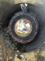
The rodent had literally eaten the insulations on the wire leads for the motor / Generator.
So I completely replaced all of the wiring for the Motor / Generator, the Exciter and the DC motor and did a full rebuild on all of it in my home garage.

Since I already had the 3Phase AC motor apart, I figured it only made since to split the internal star point apart, and bring those wire leads out, so instead of having a 9 lead motor (common) I know have a 12 lead motor. This put me in an interesting position, to do a Steelman method of converting the lathe from #phase to single phase, or allowed me to do a Low-voltgage conversion using a a Starting circuit. Turns out both methods use the same starting circuit.

The main difference is the Steelman method specs out a 60uF run capacitor, and the Low Voltage method (common on a rotor phase convertor) uses a 100 uF run capacitor.

The smaller 60uF run cap has a 8mm mounting thread, where as the larger 100uF cap uses 12mm. So I used an 8 to 12mm thread adapter, so I can easily interchange both caps, to test both methods.
To better facilitate testing both methods and taken measurements, I set up a third terminal strip and ran jumper wires.

I then set up two multi meters, one is reading voltage across the coil of the relay that takes the start cap out of the run circuit. The second is measuring resistance across the relays's switched contacts.
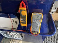
The idea is when the motor comes up to speed, the relay should drop the start cap out of the circuit and the reistance across the relay's switched contacts should read as an open circuit. Until it comes up to speed it should show some resistance.
It's now time to fire up the lathe for a test.
It F'n works! It fired right up on first try!
As you can see in the video the Relay's switch opens up very quickly as the motor comes up to full speed almost instantly. Note the 400+V across the relay's coil. This is proving to me the original Supco APR5 relay recommend for the Steelman method is undersized, as that relay is only rated for 250V.
To better evaluate the two methods of converting the 3Phase motor to single phase I purchased a Picoscope 2204A Oscilloscope. The nice thing about this unit is it works with both PC's and Mac's which is goos as I only run Apple computers and have for the last 20+ years. It also has some pretty sophisticated software, that I have a lot to learn about.

Here is the test setup

Cal Haines over on Practical Machinist, came up with a series of test perimeters for me to evaluate, consisting of 8 runs on the Steelman conversion and 11 run on the Low-Voltage singe phase conversion setup. Since the scope only has two Chanels, we are leaving the first challenge to take the T1 voltages, and then using the second Chanel to do the other measurements, this way we can sue the T1 channel as a reference to compare each. This will allow us to look as each set of of windings in the motor separately for both voltage and amperage measurements.
For example, here is an overlay of the voltages of the T1, T2 and T3 winding sets in the Steelman conversion. Hopefully I have the overlays properly aligned.
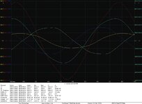

Notice how much stronger the T3 set is. I think this makes sense as its in series while the T1 and T2 sets in the configuration have the motor coils in parallel.
I haven't used a scope since I had a few EE classes in college and thats 20+ years ago at this point, so I kinda fell like I am learning it all again from scratch. So always open to any insights.
I was also going to setup a set of 3 thermal couples to take measurements of how hot the motor windings got, but I totally forgot. So I will have to implement that in the next series of testing.
The rodent had literally eaten the insulations on the wire leads for the motor / Generator.
So I completely replaced all of the wiring for the Motor / Generator, the Exciter and the DC motor and did a full rebuild on all of it in my home garage.
Since I already had the 3Phase AC motor apart, I figured it only made since to split the internal star point apart, and bring those wire leads out, so instead of having a 9 lead motor (common) I know have a 12 lead motor. This put me in an interesting position, to do a Steelman method of converting the lathe from #phase to single phase, or allowed me to do a Low-voltgage conversion using a a Starting circuit. Turns out both methods use the same starting circuit.
The main difference is the Steelman method specs out a 60uF run capacitor, and the Low Voltage method (common on a rotor phase convertor) uses a 100 uF run capacitor.
The smaller 60uF run cap has a 8mm mounting thread, where as the larger 100uF cap uses 12mm. So I used an 8 to 12mm thread adapter, so I can easily interchange both caps, to test both methods.
To better facilitate testing both methods and taken measurements, I set up a third terminal strip and ran jumper wires.
I then set up two multi meters, one is reading voltage across the coil of the relay that takes the start cap out of the run circuit. The second is measuring resistance across the relays's switched contacts.
The idea is when the motor comes up to speed, the relay should drop the start cap out of the circuit and the reistance across the relay's switched contacts should read as an open circuit. Until it comes up to speed it should show some resistance.
It's now time to fire up the lathe for a test.
As you can see in the video the Relay's switch opens up very quickly as the motor comes up to full speed almost instantly. Note the 400+V across the relay's coil. This is proving to me the original Supco APR5 relay recommend for the Steelman method is undersized, as that relay is only rated for 250V.
To better evaluate the two methods of converting the 3Phase motor to single phase I purchased a Picoscope 2204A Oscilloscope. The nice thing about this unit is it works with both PC's and Mac's which is goos as I only run Apple computers and have for the last 20+ years. It also has some pretty sophisticated software, that I have a lot to learn about.
Here is the test setup
Cal Haines over on Practical Machinist, came up with a series of test perimeters for me to evaluate, consisting of 8 runs on the Steelman conversion and 11 run on the Low-Voltage singe phase conversion setup. Since the scope only has two Chanels, we are leaving the first challenge to take the T1 voltages, and then using the second Chanel to do the other measurements, this way we can sue the T1 channel as a reference to compare each. This will allow us to look as each set of of windings in the motor separately for both voltage and amperage measurements.
For example, here is an overlay of the voltages of the T1, T2 and T3 winding sets in the Steelman conversion. Hopefully I have the overlays properly aligned.
Notice how much stronger the T3 set is. I think this makes sense as its in series while the T1 and T2 sets in the configuration have the motor coils in parallel.
I haven't used a scope since I had a few EE classes in college and thats 20+ years ago at this point, so I kinda fell like I am learning it all again from scratch. So always open to any insights.
I was also going to setup a set of 3 thermal couples to take measurements of how hot the motor windings got, but I totally forgot. So I will have to implement that in the next series of testing.
Last edited: