To avoid these ads, REGISTER NOW!

Help with circuit board resistor

MattVette89

Well-known member
Joined
Nov 27, 2014
Messages
2,265
Location
SW Chicago
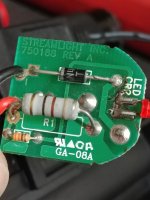
Hey guys, hoping you can point me in the right direction. This is for my Streamlight charger. The piggyback portion doesn't work. I think I've narrowed it down to this resistor. I can do the replacement but with limited experience I want some help identifying the right part to get.

The charger itself reads:
Input 12-15vdc .2A
Main out regulated .18A
Aux out 3.6vdc .14A

It seems to be a 4 band. I've used the online calculator but not sure if I have the right colors.

Any help is appreciated.
 

Attachments

  • 20181206_102745.jpg
    20181206_102745.jpg
    86.9 KB · Views: 103
  • 20181206_102833.jpg
    20181206_102833.jpg
    73.8 KB · Views: 115
  • 20181206_102840.jpg
    20181206_102840.jpg
    77.6 KB · Views: 109
  • 20181206_103039_HDR.jpg
    20181206_103039_HDR.jpg
    73.6 KB · Views: 111
To avoid these ads, REGISTER NOW!

dogdog

Well-known member
Joined
Nov 15, 2011
Messages
12,711
looks to me it's a 41 OHM 1/2 watt maybe 1 watt current limiting resistor... most like a 1 watt one... I thought steam light have life time warranty on their thing... if your cells are 10650 just google it.

if your cell is a single cell lithium ion battery, you are better off buying a charger from ebay... cheaper.


not even a cheapo micro chip charge controller for the price of that thing... hmmm cheesy...
 

RPH

Well-known member
Joined
Dec 17, 2006
Messages
4,190
Location
Michigan Thumb
What makes you think the resister is the problem? Most of the ones that I have found have been cooked, some more than others! Only a few times on equipment that was twenty plus years old have I seen resistors drift enough to affect circuit operation. Other components tend to be more unstable. Is something else dragging the power supply down? Have you isolated things?
 

jismay

Well-known member
Joined
Oct 6, 2013
Messages
96
Agreed, it should be a 41ohm current limiting resistor. Have you put a meter across it and checked the resistance?

Those sort of resistors are unlikely to just drift, they should be relatively close to spec or completely open. Honestly, for that application even the specific resistance probably isn't all that important as long as its in the ballpark, so al long as the resistor isn't either open or dead-short then I would look elsewhere. Have you verified that the diode is working as expected? You can use the continuity feature of a multimeter on a diode (or an LED for that matter) it will only beep with the leads in one direction, so check it one way then switch the leads and check the other.
 

theoldwizard1

Well-known member
Joined
Feb 22, 2011
Messages
43,106
Location
SE MI
Those sort of resistors are unlikely to just drift, they should be relatively close to spec or completely open.
The fourth band is gold so it is a 5% resistor.

As stated, a bad resistor usually has "let the magic smoke out" and leaves an obvious burn mark on the board.
 

MikeF2316

Well-known member
Joined
Dec 29, 2012
Messages
9,605
Location
Thornhill, ON
It looks like white brown black gold to me. That would make it 91 ohms, +/- 5%. Note that 91 is an IEEE 5% standard value whereas 41 isn't.
 

LXCam

ALLIANCE MEMBER
Joined
Apr 23, 2013
Messages
19,092
Location
AZ
I'd suggest looking at the other side of the board adjacent to that diode at the led. That looks like it got hot.
 

dogdog

Well-known member
Joined
Nov 15, 2011
Messages
12,711
It looks like white brown black gold to me. That would make it 91 ohms, +/- 5%. Note that 91 is an IEEE 5% standard value whereas 41 isn't.

41 OHM makes more sense if it is used as a voltage dropper from 12-15v down to a voltage that is safe for the zener diode as a voltage regulator.... that is for the aux out 3.6V @ .14A

and besides that pic 3 and 4 shows more yellow than white... at least on my screen it is....
 

Stuart in MN

Well-known member
Joined
Sep 8, 2005
Messages
23,036
Location
Minneapolis
I'd suggest looking at the other side of the board adjacent to that diode at the led. That looks like it got hot.

I think you may simply be seeing the shadow lines of the PC board traces on the back side.

If all there is on this board are those two resistors and a diode, even using the parts cannon method and replacing all three components won't cost much.
 
To avoid these ads, REGISTER NOW!
OP
M

MattVette89

Well-known member
Joined
Nov 27, 2014
Messages
2,265
Location
SW Chicago
Edit - I think MikeF is correct. I rechecked and now it's testing around 90 ohms. From moving things around it seems like cold solder joints could be to blame.

Thanks for the help, guys.

The charger is over 13 years old, by the way
 
Last edited:

LXCam

ALLIANCE MEMBER
Joined
Apr 23, 2013
Messages
19,092
Location
AZ
I think you may simply be seeing the shadow lines of the PC board traces on the back side.

If all there is on this board are those two resistors and a diode, even using the parts cannon method and replacing all three components won't cost much.

Quite possible. I still haven't mastered the art of seeing details off a phone. And then there's that glasses thing, it's well past time for a new prescription. :headscrat
 

MikeF2316

Well-known member
Joined
Dec 29, 2012
Messages
9,605
Location
Thornhill, ON
Edit - I think MikeF is correct. I rechecked and now it's testing around 90 ohms. From moving things around it seems like cold solder joints could be to blame.

Thanks for the help, guys.

The charger is over 13 years old, by the way

Keep in mind there can be an intermittent between the guts of the resister and the lead that you see sticking out. I've seen that more than once.
 

MikeF2316

Well-known member
Joined
Dec 29, 2012
Messages
9,605
Location
Thornhill, ON
41 OHM makes more sense if it is used as a voltage dropper from 12-15v down to a voltage that is safe for the zener diode as a voltage regulator.... that is for the aux out 3.6V @ .14A

and besides that pic 3 and 4 shows more yellow than white... at least on my screen it is....

I guessed white over yellow because 91 is a IEEE 5% value and 41 isn't. It doesn't look yellow enough to be yellow, but too yellow to be white.
 

Bert_

Well-known member
Joined
Dec 24, 2016
Messages
9,702
Location
NW Iowa
Cracked solder joints is a problem fairly often. I'm not real well versed with electronics repair, but I have fixed thousands of dollars worth of stuff just by reflowing the solder joints. Or other simple stuff.

If you can tap on it and have it work for a while it is almost certainly a cracked solder joint.
 
To avoid these ads, REGISTER NOW!
Top Bottom