To avoid these ads, REGISTER NOW!

Help with three phase motor wiring

Ecosta777

Well-known member
Joined
Apr 26, 2016
Messages
271
Location
MA
Normally I'm ok with typical household electric stuff, but when it comes to motors and especially drum switches, I just seem to be in the dark. Also, I've never dealt with three phase power before.

I have a three phase motor for a Bridgeport shaper head. I have a VFD to run it off of. As far as the VFD goes I'm ok there, it's what come 'after' so to speak I need help with. Once the three phase power comes out of the VFD I'm lost.

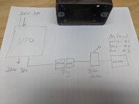
I'm going from the VFD to an extension with a plug which will allow me to plug in other things instead of hardwiring to the shaper head. Then the shaper head will plug into that and have an on off switch mounted to it.

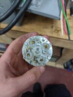
So how do I know which wires are W, X, Y ,Z? I have made note of which wires in the motor were attached to which colors before I fixed the motor up. Also shown is the presumably original switch box, but there was no switch when I bought it, just hardwired. But that was also to a jury rigged setup to show the motor under power when I bought it, no plug was attached, just hardwired. I'm also unsure of what goes to what poles on the drum switch. I don't need reversing capability, so the switch is just an on/off

I've attached a sketch of what I'm attempting to do, as well as some photos of the drum switch I need help with, and the plugs I'm using.

fea3ccb88a0e24979396f2194e05736a.jpgd37af56168f70f44164b16e2326fb87c.jpgc425c6fc3dc184483352cbacfc4278ca.jpgad072240dbd7ddba56f06ab3da7220a6.jpgdf6152d7e507976b0e5e4beeb754845e.jpg0f719a501b5c0f81d51633f9c5f4aab6.jpg78ad15349d7bdbbebf76d6815d2b304d.jpg27dee18236bdfc18a31200bd58707cf4.jpga84403592e9ce7d9f2266debc525ef84.jpg9acaa282f68433ebbbb44126c8f3b6be.jpg

Sent from my Pixel 2 using Tapatalk
 

Attachments

  • fea3ccb88a0e24979396f2194e05736a.jpg
    fea3ccb88a0e24979396f2194e05736a.jpg
    50.1 KB · Views: 0
  • d37af56168f70f44164b16e2326fb87c.jpg
    d37af56168f70f44164b16e2326fb87c.jpg
    49.6 KB · Views: 0
  • c425c6fc3dc184483352cbacfc4278ca.jpg
    c425c6fc3dc184483352cbacfc4278ca.jpg
    51.1 KB · Views: 0
  • ad072240dbd7ddba56f06ab3da7220a6.jpg
    ad072240dbd7ddba56f06ab3da7220a6.jpg
    57.6 KB · Views: 0
  • df6152d7e507976b0e5e4beeb754845e.jpg
    df6152d7e507976b0e5e4beeb754845e.jpg
    57.1 KB · Views: 0
  • 0f719a501b5c0f81d51633f9c5f4aab6.jpg
    0f719a501b5c0f81d51633f9c5f4aab6.jpg
    56.7 KB · Views: 0
  • 78ad15349d7bdbbebf76d6815d2b304d.jpg
    78ad15349d7bdbbebf76d6815d2b304d.jpg
    109.2 KB · Views: 0
  • 27dee18236bdfc18a31200bd58707cf4.jpg
    27dee18236bdfc18a31200bd58707cf4.jpg
    62.7 KB · Views: 0
  • a84403592e9ce7d9f2266debc525ef84.jpg
    a84403592e9ce7d9f2266debc525ef84.jpg
    33.7 KB · Views: 0
  • 9acaa282f68433ebbbb44126c8f3b6be.jpg
    9acaa282f68433ebbbb44126c8f3b6be.jpg
    82.8 KB · Views: 0
To avoid these ads, REGISTER NOW!

Norcal

Well-known member
Joined
Mar 16, 2008
Messages
13,752
That plug/ connector is not correct as they are dual voltage non-grounding devices and if someone says they are fine that is flat wrong there are a large number of configurations provided by NEMA for the voltage, amperes, single or 3 phase needed, just because someone had it, or was cheap is not a legitimate reason to use the wrong one. Breaking the line between the motor and VFD is a good way to let the smoke out of the drive, but the drum switch could be used to control forward and reverse through the drive.
 

wyliesdiesels

Well-known member
Joined
Aug 14, 2012
Messages
19,994
Location
Modesto, CA
Forget the switch or any other controls between the VFD and motor.

You will cause problems if you put stuff in between the VFD and motor.

Also what voltage are you running at?

Looks like the plug is 208v. BTW that is NOT a ‘Z’ it is an ‘N’ meaning neutral. So that is the wrong plug. 200v(208v) 230v(240v) and 460v(480v) motors do not need a neutral.

You need a 3 pole grounded plug rated for the same voltage as the voltage youre running.
 
Last edited:

Strouty

Well-known member
Joined
Mar 21, 2010
Messages
38,212
Location
Southern Maine
Usually when you use a VFD, it is wired one per motor, people don't usually use them like a phase converter for all equipment. How many more pieces of equipment do you have? I have a decent sized rotary phase converter (RPC) for my entire shop (not yet wired up), currently I am running a small (5 hp idler) RPC that is setup to do one piece of equipment at a time. Wiring things up a RPC can run more than one thing at once assuming there is enough idler to put out the power needed.
 

MattT

Well-known member
Joined
Feb 20, 2010
Messages
3,201
In addition to the above ^^^^^^^ that enclosure looks way to small and will likely cook the drive.
 
OP
E

Ecosta777

Well-known member
Joined
Apr 26, 2016
Messages
271
Location
MA
That plug/ connector is not correct as they are dual voltage non-grounding devices and if someone says they are fine that is flat wrong there are a large number of configurations provided by NEMA for the voltage, amperes, single or 3 phase needed, just because someone had it, or was cheap is not a legitimate reason to use the wrong one. Breaking the line between the motor and VFD is a good way to let the smoke out of the drive, but the drum switch could be used to control forward and reverse through the drive.
Thanks, I had just grabbed this plug from work assuming it was correct. I'll make sure to get the right one

Sent from my Pixel 2 using Tapatalk
 
OP
E

Ecosta777

Well-known member
Joined
Apr 26, 2016
Messages
271
Location
MA
Usually when you use a VFD, it is wired one per motor, people don't usually use them like a phase converter for all equipment. How many more pieces of equipment do you have? I have a decent sized rotary phase converter (RPC) for my entire shop (not yet wired up), currently I am running a small (5 hp idler) RPC that is setup to do one piece of equipment at a time. Wiring things up a RPC can run more than one thing at once assuming there is enough idler to put out the power needed.
I have the shaper head, and an M head. In this case of the shaper it will just be a phase converter. But when I use the M head I'll be using the VFD for high speed / small cutting tools

Sent from my Pixel 2 using Tapatalk
 
OP
E

Ecosta777

Well-known member
Joined
Apr 26, 2016
Messages
271
Location
MA
Why can't I use a switch after the converter? I don't understand why that's bad. I'm simply stopping the 3 phase power coming out of the VFD until I'm ready to turn the machine on. The VFD will be mounted on the wall far away from the working area, and I don't want to have to run to the wall of something happens and I need to turn off the machine.
The M head has a switch on it already, and I don't want to hardwire the VFD to either machine because they'll both be used.
I understand that a VFD is not necessarily a phase convert but when you can't afford a nice phase converter you have to work with what you have....

Sent from my Pixel 2 using Tapatalk
 

Norcal

Well-known member
Joined
Mar 16, 2008
Messages
13,752
You might get away with switching between the drive and the motor a few times but your luck will run out and you will have fried the drive, then you get to buy another, they just don’t like having the output switched, all switching must be done through the drive.
 

Mr. T

Well-known member
Joined
Sep 4, 2013
Messages
636
Location
Central PA
Thanks, I had just grabbed this plug from work assuming it was correct. I'll make sure to get the right one

Sent from my Pixel 2 using Tapatalk


You should have ZERO plugs and switches between your VFD and motor. If your VFD is switched on without a load it will release the magic smoke.
 

rlitman

Well-known member
Joined
Oct 18, 2010
Messages
24,583
Location
Long Island
...BTW that is NOT a ‘Z’ it is an ‘N’ meaning neutral...

While I agree that it is a neutral, all of the diagrams I can find list it as a Z, and even in the picture, it is clearly a Z and not an N.

Hubbell does at least use a silver colored screw and blade for the Z terminal, unlike Leviton.
 

wyliesdiesels

Well-known member
Joined
Aug 14, 2012
Messages
19,994
Location
Modesto, CA
Why can't I use a switch after the converter? I don't understand why that's bad. I'm simply stopping the 3 phase power coming out of the VFD until I'm ready to turn the machine on. The VFD will be mounted on the wall far away from the working area, and I don't want to have to run to the wall of something happens and I need to turn off the machine.
The M head has a switch on it already, and I don't want to hardwire the VFD to either machine because they'll both be used.
I understand that a VFD is not necessarily a phase convert but when you can't afford a nice phase converter you have to work with what you have....

Sent from my Pixel 2 using Tapatalk

You cant put a switch in between the VFD and the motor because you will burn it up. VFDs do not like the load on their output being opened like what happens when there is a switch.

Also, you said youre "simply stopping the 3 phase power coming out of the VFD until I'm ready to turn the machine on." That is incorrect as you would not be stopping the power with an inline switch. That is only done via the VFD low voltage controls. The VFD would still be outputting power. You're just interrupting the power from going to the motor.

If you want to remotely control the VFD output then wire up a remote to the VFD control terminals. This is done all the time. Its not hard.
 
Last edited:
To avoid these ads, REGISTER NOW!

matt_i

Well-known member
Joined
Mar 14, 2008
Messages
10,725
Location
SE Michigan
The drum switch is perfectly useable, but on the LOW VOLTAGE side of the VFD.

Use one common* pole to be the "2 wire start/stop signal" no matter which way its switched.

Use different poles on the non-center positions to be inputs to the drive for rotation direction reference.

I think you probably need 3 inputs. One for RUN, One for FWD rotation and One for REV rotation.

The comments about the enclosure being too small are correct imo. Either go bigger or run it "open". I would use the VFD for both your main spindle and the shaper head motor. I would just land either sets of T1,T2,T3 wires manually on the terminal strip depending on what you want to use.

* the Common I'm speaking of is a 5vdc, 10vdc or 24vdc source signal that originates from the "mini terminal strip" on the VFD.
 

Paperman

Well-known member
Joined
Feb 19, 2014
Messages
148
Location
On the shore of LK Michigan
That plug/ connector is not correct as they are dual voltage non-grounding devices and if someone says they are fine that is flat wrong there are a large number of configurations provided by NEMA for the voltage, amperes, single or 3 phase needed, just because someone had it, or was cheap is not a legitimate reason to use the wrong one. Breaking the line between the motor and VFD is a good way to let the smoke out of the drive, but the drum switch could be used to control forward and reverse through the drive.


Can you school us on whats wrong with the plug?

3 phases and a ground?
 

rlitman

Well-known member
Joined
Oct 18, 2010
Messages
24,583
Location
Long Island
How-to-wire-outlets-15-750.jpg
 

walta

Well-known member
Joined
Jan 13, 2017
Messages
2,309
Location
Dutzow Missouri
Have a look at the programming instructions you will find several different options for low voltage controls. Pick the one that suits your needs. I like a NO start button a NC stop button a 3 position switch for direction FWR-Off-Rev and a speed control knob. You will likely need to change the programming setting to this profile.

As everyone else said no breaks in the wire from the VFD to the motor, no plugs, no switches and no overloads just a single length of wire.

If you like the way the way the drum switch looks or works you can connect it to the low voltage wires and use it to control the machine.

Walta
 

Norcal

Well-known member
Joined
Mar 16, 2008
Messages
13,752
Diagram's terminology confused me. W is system ground, which is really neutral, not safety ground.

There is a grounded conductor (neutral) and a grounding conductor, forget system ground and safety ground.
 

rlitman

Well-known member
Joined
Oct 18, 2010
Messages
24,583
Location
Long Island
Incorrect

A neutral is NOT a system ground.

Agreed. The diagram is showing that the white conductor is SOMEWHERE connected to the system ground for reference voltage.

Anyway, to be clear, pretty much all NEMA non-grounding connectors are obsolete. They're made and sold to repair existing equipment, and the plugs can be used on double-insulated stuff (you really only see this on 5-15 plugs), but it's not a common use case any more on anything else.
 

wyliesdiesels

Well-known member
Joined
Aug 14, 2012
Messages
19,994
Location
Modesto, CA
The white conductor/neutral/grounded conductor connects to the neutral lug on the transformer in the diagram.

The transformer neutral lug is also connected to a grounding electrode.

It is also bonded to a grounding electrode and equipment grounds at the main service panel or main disconnect.

Still, its NOT a system ground.
 
To avoid these ads, REGISTER NOW!
Top Bottom