To avoid these ads, REGISTER NOW!

Help with understanding truss bracing

egertk

Well-known member
Joined
Aug 22, 2008
Messages
58
So due to being in seismic category D2 here in the just north of Seattle area and having 12' tall walls on my new garage/shop, the engineering requirements are way more than I was expecting.
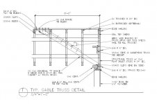
I'm trying to understand this detail that my engineer added to my plans but having a hard time visualizing all of the framing and bracing that's going on here. Does anybody have a picture or two that could help me understand this requirement?
Also, the structural truss specified here I believe is a scissor truss but with gable end vertical framing spliced in with metal connector plates?
Thank you!
 

Attachments

  • TrussDetail.jpg
    TrussDetail.jpg
    46.8 KB · Views: 129
To avoid these ads, REGISTER NOW!

matt_i

Well-known member
Joined
Mar 14, 2008
Messages
10,726
Location
SE Michigan
I think I understand, but I would have a hard time seeing how that is going to work with a scissor truss.

The angled "T" brace is just a diagonal member stiffened in cross-section by the added top of the "T" so it doesn't buckle thru the center when loaded in compression.

Looks like you nail blocking between the trusses near the top and then nail the face of the diagonal member to that. It doesn't look quite as stout near the bottom but since the 90 degree face cut is trapped in a corner not as much bracing is needed.

Not trying to supercede your engineering, but I used the Simpson "TBD22" X-bracing on both roof faces to add additional tip-over stability to my build (not required by mfg). That would seem to work better for a scissor truss.

https://www.strongtie.com/spacingrestraintandbracingproducts_platedtrussconnectors/tbd_brace/p/tbd
 

readhead

Well-known member
Joined
Dec 8, 2012
Messages
6,177
Location
Durango, Co.
That would be a difficult detail with scissor trusses. You weren't really clear. Do you have scissor trusses? The 10' on center is confusing. Is that continuous the length of the building or laterally at the gable. I suspect the latter. A plan view would probably clarify the detail.
 
To avoid these ads, REGISTER NOW!

The Tool Tyrant

ALLIANCE MEMBER
Joined
Dec 19, 2011
Messages
2,182
Location
Bonita, Ca. (San Diego)
Check w/ your structural engineer, that is a very confusing detail...and I was a framing contractor for 32 years! I believe he has some mis-labeling.
There are no scissor trusses. The 'structural' truss on the wall, just means that it's a standard truss with vertical fill rather than a 'Gable end truss' that would only have vertical fill and is not designed to transfer loading to the end points.
 

Radix2

Well-known member
Joined
May 28, 2014
Messages
1,853
Location
the thumb!, MI
Typically, the truss company will send a drawing of the actual requirements with the trusses, assuming they designed the trusses for your building. It will specify bracing requirements, lineal to be added, which trusses go where, etc.
 

The Tool Tyrant

ALLIANCE MEMBER
Joined
Dec 19, 2011
Messages
2,182
Location
Bonita, Ca. (San Diego)
Typically, the truss company will send a drawing of the actual requirements with the trusses, assuming they designed the trusses for your building. It will specify bracing requirements, lineal to be added, which trusses go where, etc.

^^ This is true, BUT... the Structural Engineer of record (whose stamp is on your approved plans) has last word on specific structural requirements for said project and his details always supersede standard bracing details supplied by the truss manufacturer.
 

RocketScott

Well-known member
Joined
Jul 20, 2016
Messages
262
Location
Lexington, KY
Radix2 is right. That detail is just the generic detail the engineer throws into the plan (It's not uncommon to have a plan with multiple pages of details and only half of them are used). This one in particular basically says "look to someone else for how to build this part"

Generally go with what the truss company specifies. The truss company should take all the engineering requirements into account when they design and build the trusses. There will be a packet of general info stapled with the individual truss specs that details what bracing is needed. For gables the requirements are based on how tall the truss is and how close together the vertical members are. Your engineer calls out 24" oc stud spacing on the gable but the truss company might decrease that to 16" or even 12", sometimes only in the middle of the truss, in order to meet the requirements most effectively.

That's why the engineer wrote on the detail what I've circled in red. I love how he has the notes pointing to the wrong object in the diagram and that he called out a 1 to 1 pitch on the brace (45 degrees) but also calls out the top to be 8' from the gable and the bottom to be on top of plate. Those two bits contradict each other for anything other than an 8' tall gable. Typ.

TrussDetail.png
 
To avoid these ads, REGISTER NOW!
Top Bottom