To avoid these ads, REGISTER NOW!

Help with wiring a DC Motor

dacalkins

Member
Joined
Sep 14, 2022
Messages
16
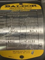
I purchased a used Baldor CD 3475 DC motor to be used with a KB controls KBMD controller. The DC motor has 6 wires (not 3 that I'm used to) A1, A2, F1, F2, F3, F4.

I will be attaching the A1 and A2 to the A+ and A- depending on CCW or CW of the motor shaft. However, I'm confused by the remaining 4 wires F1 etc. According to the wiring diagram on the motor there are two wiring options Hi or low voltage. Which one do I want for a 110v line input? Ultimately, I need a F+ and F- for the controller.

Thanks

David
 

Attachments

  • 20220914_135940.jpg
    20220914_135940.jpg
    324.9 KB · Views: 46
  • 20220914_135855.jpg
    20220914_135855.jpg
    162.5 KB · Views: 33
  • 20220914_135910.jpg
    20220914_135910.jpg
    204.4 KB · Views: 35
To avoid these ads, REGISTER NOW!

banditbigdog

Well-known member
Joined
Jan 3, 2009
Messages
271
Location
Southeast
Appears the field winding(s) can be energized by 50vdc (low), or 100 vdc (high).
You mention 110v, that designation to me is “common” to 110 vac or 110 volts ac.
Do not connect the field windings of this motor to ac voltage.

Info on the motor:


Info on field windings:

 
OP
D

dacalkins

Member
Joined
Sep 14, 2022
Messages
16
Sorry but This is all new to me. If I have a 110 outlet should I wire to low or hi voltage for the "F" wires?
 

banditbigdog

Well-known member
Joined
Jan 3, 2009
Messages
271
Location
Southeast
The motor in question is a direct current motor (dc).
It will not operate from a “110 outlet” if that 110 outlet is in fact supplying 110 volts alternating current or “ac”

The motor in question uses direct current, either 50 volts dc -or- 100 dc volts applied to the field terminals to create a magnetic field.

Very common to see dc motors of this size use permanent magnets to create a desired (correct) magnetic field surrounding the armature.

Not so common to see DC motors of this size using dc current (electromagnet) to create a magnetic field surrounding the armature.

Obviously they exist and serve a purpose but again, not as commonly seen as a dc motors utilizing permanent magnets as the “field”.
 

LXCam

ALLIANCE MEMBER
Joined
Apr 23, 2013
Messages
19,097
Location
AZ
You need a dc drive module sized correctly to your motor.

This is basically it

6F25F58C-F5CB-409D-9C9B-4C1037279564.png4748C71F-6458-470D-814B-5E1316154560.png
 
OP
D

dacalkins

Member
Joined
Sep 14, 2022
Messages
16
I'm using the KBMT 240 with the appropriate resistors. I specifically chose this motor & controller because that is what Mr Pete used on his drill press. Unfortunately for me he was rather vague on how to wire it up.


Attachments

  • kbmd_240d.pdf
    3.2 MB · Views: 8

Grant Gunderson

Well-known member
Joined
May 17, 2013
Messages
2,319
Location
Bellingham, WA
Sorry but This is all new to me. If I have a 110 outlet should I wire to low or hi voltage for the "F" wires?
Do NOT connect tgat motor to 110vac coming from your wall!

That motor requires a DC power supply that converts form ac to dc. Looks like you bought one with a speed control built in. That’s good. You need to read that manual though.

It’s very clear that if your power supply is outputing the low-range DC voltage then wire F1 and F3 together then to power supplies Field F2 and F4 get wired together than to power supplies other Field.

Your power supply outputs 180vdv. So if according to your motor that is what it considers high voltage then you wire f1 and F 4 to it. F2 and F3 get wired together on the motor.

But first you need to confirm that your motor is shunt wound. Secondly you need to see what the motor specifies as being high vs low voltage. That info should all be on the motors name plate.

Read page 7 and 8 on your manual for ac hookup to the power supply / speed controler you bought. since you are running it off of 110vac and not 230vdc.

Remember DC stands for deadly current. If you are at all unsure higher an electrician or take it to a motor shop.

One last thing make sure all of your wire is rated for the Apropriate DC voltage and current it’s a different rating than it is for AC.
 
To avoid these ads, REGISTER NOW!
OP
D

dacalkins

Member
Joined
Sep 14, 2022
Messages
16
Please find the ID plate from my motor. Thanks for all your help
 

Attachments

  • Baldor DC motor.jpg
    Baldor DC motor.jpg
    320.1 KB · Views: 31

Grant Gunderson

Well-known member
Joined
May 17, 2013
Messages
2,319
Location
Bellingham, WA
Please find the ID plate from my motor. Thanks for all your help
Your image is cropped, so its tough to read all of the name plate, but it looks like your motor is 100VDC for High voltage and 50VDC for low for the Field and should see a Max of .6 or 1.2 Amps for the field and a max if 7.8 for the Arm. Doesn't your DC converter / motor control output 180VDC?

So you need to wire the motor in the High Voltage configuration. You also need to see how to configure the DC control so it outputs a max of 100VDC. Ideally 90 VDC

Here right on page 3 of your motor controller manual:

3 – DUAL VOLTAGE SWITCH SETTING
The control is factory set for 230 Volt AC Line input (Dual Voltage Switch set to the "230" position), for use with 180 Volt motors. For 115 Volt AC Line input, for use with 90 Volt Motors, set the Dual Voltage Switch to the "115" position. See Section 7 on page 7.
 
OP
D

dacalkins

Member
Joined
Sep 14, 2022
Messages
16
1663512875188.png

Thanks everyone for your help. This is what I have concluded from all of your input. I have also sent this over to an electrician for his concurrence
 
To avoid these ads, REGISTER NOW!
Top Bottom