To avoid these ads, REGISTER NOW!

Help with wiring a Sonoff POW CT meter in subpanel

WI/MI Border

Well-known member
Joined
Jan 27, 2025
Messages
196
I am trying to collect some electrical use data on a new garage with a 100a subpanel. I want three or four months of electrical usage to calculate a solar system to power the garage off grid. If you have any experience with the Sonoff POW CT please chime in and let me know how this may work.

I have two of the meters and I'm confused about how to measure both 110v legs of the 100a panel. I know how to connect power to the Sonoff meters. And I understand how to clip the CT on the feed. That's fairly straight forward. What I don't know is do I need to have a meter on both 110v feeds? And do I add the two kWh together from each meter to get actual power consumption?

Thanks. Reply as though I am a seventh grader : )
 
To avoid these ads, REGISTER NOW!

mm08822

Well-known member
Joined
Jan 13, 2012
Messages
6,051
Location
NJ
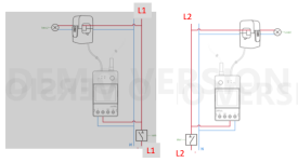
If you want accurate measurements when there are multiple 120v loads across both legs (L1 and L2) you will need 2 of these meters.
Using this diagram, wire both meters to each leg independent of the other. ("L" becomes "L1" and "L2")
1768926009554.png
Yes, total consumption is the sum of both meter measurements. (1+1=2 :lol:)
 
Last edited:
OP
W

WI/MI Border

Well-known member
Joined
Jan 27, 2025
Messages
196
If you want accurate measurements when there are multiple 120v across both legs (L1 and L2) you will need 2 of these meters.
Using this diagram, wire both meters to each leg independent of the other. ("L" becomes "L1" and "L2")
1768926009554.png
Yes, total consumption is the sum of both meter measurements. (1+1=2 :lol:)
Thank you very much mm08822! I managed to get those working with no problems. I'm hopefully on my way to collecting monthly data so I can create an off grid solar package that fits my needs I appreciate the help.

Tim

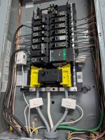
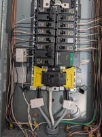
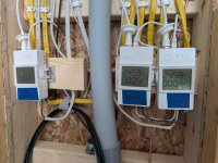
On the left is my mini split metering. On the right are the two legs on main feeds. I don't need access to read them as long as I have the eWeLink app.

1000001015.jpg


1000001014.jpg
 

PCustoms

Well-known member
Joined
Jul 23, 2011
Messages
23,453
Location
VT
Thank you very much mm08822! I managed to get those working with no problems. I'm hopefully on my way to collecting monthly data so I can create an off grid solar package that fits my needs I appreciate the help.

Tim

On the left is my mini split metering. On the right are the two legs on main feeds. I don't need access to read them as long as I have the eWeLink app.

1000001015.jpg


1000001014.jpg


What kind of wire feeds that panel?

What wire is coming off the 2 240v breakers on the left?
 

mm08822

Well-known member
Joined
Jan 13, 2012
Messages
6,051
Location
NJ
What kind of wire feeds that panel?

What wire is coming off the 2 240v breakers on the left?

is that cordage coming off the breakers on the left?
It's OP's temp power to each power monitor. He's looking for 3-4 mos of data. Then we can assume it is removed as are all temporaries.

The grey conductors need to be at least re-identified.
 

PCustoms

Well-known member
Joined
Jul 23, 2011
Messages
23,453
Location
VT
It's OP's temp power to each power monitor. He's looking for 3-4 mos of data. Then we can assume it is removed as are all temporaries.

I sort of see it now...

But there's 3 monitors, and 2 cords. Also doesn't monitornuse a CT? Is this for 120v to power the monitor, or is it fed through?

Looks wrong to me.


The grey conductors need to be at least re-identified.

I'm curious what that is, as it seems odd to me
 

mm08822

Well-known member
Joined
Jan 13, 2012
Messages
6,051
Location
NJ
I sort of see it now...

But there's 3 monitors, and 2 cords. Also doesn't monitornuse a CT? Is this for 120v to power the monitor, or is it fed through?

Looks wrong to me.


I'm curious what that is, as it seems odd to me
He jumpered from "1" to "2" below outside the panel.
He has 3 split core ct's in the panel.....the white plastic covered cores. Each has a cable going to the respective monitor.

The grey conductors remind me of Olflex cable conductors, which was similar to a MTW (not saying it is).
 

PCustoms

Well-known member
Joined
Jul 23, 2011
Messages
23,453
Location
VT
He jumpered from "1" to "2" below outside the panel.
He has 3 split core ct's in the panel.....the white plastic covered cores. Each has a cable going to the respective monitor.

Again, I understand the ct's

Not clear why he would run cord into the panel and tap off what appears to be a 240v breaker to feed the displays. To each their own I guess
 
To avoid these ads, REGISTER NOW!

Jlanciani

Well-known member
Joined
Jun 7, 2020
Messages
165
Location
Home
Again, I understand the ct's

Not clear why he would run cord into the panel and tap off what appears to be a 240v breaker to feed the displays. To each their own I guess
Because the meters need voltage and current to calculate watts.
 

mm08822

Well-known member
Joined
Jan 13, 2012
Messages
6,051
Location
NJ
Again, I understand the ct's

Not clear why he would run cord into the panel and tap off what appears to be a 240v breaker to feed the displays. To each their own I guess
Looks to me like 120 in each case. How else to feed the meters and assure feed power is in phase with CT? I would have just chucked all 3 in the panel being as they are temps.

Actually, OP may have messed up jumpering power from meter 1 to meter 2. (Not sure, I didn't read the manual and I would have purchased a 3-wire system anyway. Worst case, maybe watts get recorded as VA instead. Dunno)
 

wyliesdiesels

Well-known member
Joined
Aug 14, 2012
Messages
20,073
Location
Modesto, CA
looks like both main meters have 240v going to them. so i dont get why he needs 2. shouldve just gone with a 3 wire CT system with 1 meter
 

PCustoms

Well-known member
Joined
Jul 23, 2011
Messages
23,453
Location
VT
Because the meters need voltage and current to calculate watts.
Duh.

Thanks, not sure why I overlooked that

I have a bad relationship with CT from an interesting retrofit I was involved in years ago
 
OP
W

WI/MI Border

Well-known member
Joined
Jan 27, 2025
Messages
196
So many questions! But you guys nailed most of them.

Yes, temporary cord to power the meters via 220v. Instructions I saw concerning the mini split meter said I should power the meter with the same circuit as the mini split. Didn't sound "wrong" so I did it that way. That meter has been in service for about three + months. The other meter is measuring via 220v power with a temporary cord as well and yes, it will be removed in a few months. Wire is jumped from one meter to the other. I can easily fix that if that is a big concern. Those two meters were originally meant for another purpose when I decided to collect data for consumption to design a solar array.

And thanks to PCustoms, et al, back in a March post about wiring my sub panel from home panel. I used Aluminum 2 - #1 xhhw, 1 - #2 xhhw and 1 - #6 xhhw green (< 50' run). If you are wondering why they are not black feeds the supplier did not have black in stock and gave me a good deal because I used grey. If you were wondering if an inspector missed that, well, truth be told we do not have electrical inspections in my city. Yes, you read that right. We don't even have construction/building inspectors. Pay the $50 permit fee and away you go. I was very surprised by this after asking the Zoning and Permit Administrator when I should contact him to do inspections... no inspections for foundation/slab forms, carpentry rough-in, electrical, etc.

I believe I followed code on all installations and builds. With the exception of the temporary cordage. Of course even a pro makes mistakes now and then.

Thanks again for all the advice. I'm really enjoying the workshop. A lot of the success is due to many helpful members here.

Tim
 

wyliesdiesels

Well-known member
Joined
Aug 14, 2012
Messages
20,073
Location
Modesto, CA
So many questions! But you guys nailed most of them.

Yes, temporary cord to power the meters via 220v. Instructions I saw concerning the mini split meter said I should power the meter with the same circuit as the mini split. Didn't sound "wrong" so I did it that way. That meter has been in service for about three + months. The other meter is measuring via 220v power with a temporary cord as well and yes, it will be removed in a few months. Wire is jumped from one meter to the other. I can easily fix that if that is a big concern. Those two meters were originally meant for another purpose when I decided to collect data for consumption to design a solar array.

The problem with this is the cordage is finely stranded wire where as the circuit conductors are either solid or large stranded wire. this will cause a poor connection at the breaker lug. fine stranded wire is not meant to be terminated under a breaker lug.

The other issue is most breakers are not rated for 2 conductors. Sq D might be the exception but the fine stranded wire still creates an issue as you will not be able to get it correctly tightened with different types of wire.

And thanks to PCustoms, et al, back in a March post about wiring my sub panel from home panel. I used Aluminum 2 - #1 xhhw, 1 - #2 xhhw and 1 - #6 xhhw green (< 50' run). If you are wondering why they are not black feeds the supplier did not have black in stock and gave me a good deal because I used grey. If you were wondering if an inspector missed that, well, truth be told we do not have electrical inspections in my city. Yes, you read that right. We don't even have construction/building inspectors. Pay the $50 permit fee and away you go. I was very surprised by this after asking the Zoning and Permit Administrator when I should contact him to do inspections... no inspections for foundation/slab forms, carpentry rough-in, electrical, etc.

I believe I followed code on all installations and builds. With the exception of the temporary cordage. Of course even a pro makes mistakes now and then.

Thanks again for all the advice. I'm really enjoying the workshop. A lot of the success is due to many helpful members here.

Tim

gray is only permitted to be used for neutrals. you shouldve used any other color other than white green or green w/ yellow stripe(s).

the conductors on both ends (in both panels) should be taped black to indicate they are not neutrals
 
Last edited:
OP
W

WI/MI Border

Well-known member
Joined
Jan 27, 2025
Messages
196
The problem with this is the cordage is finely stranded wire...
Thanks. I'll change out both cords with 14g solid copper.
...

the conductors on both ends (in both panels) should be taped black to indicate they are not neutrals
When I rewire the meter power I'll double check but I remember taping the ends of the grey feeds with black tape. I'll double check under those plastic caps when I dig in there.
 
To avoid these ads, REGISTER NOW!
Top Bottom