To avoid these ads, REGISTER NOW!

HF 20 ton press mod ideas

Firebrick43

Well-known member
Joined
May 12, 2015
Messages
14,183
Location
West central Indiana
A good friend of mine had a nice press and several other engine rebuild tools moved after he retired.

To fill the void for things that are larger than my arbor press can handle I picked up a POS HF 20 ton press.

The plate/cross member that the bottle jack sets on is atrocious. The rest seems OK.

Rainy day here at the cabin so I drew up a new cross member.
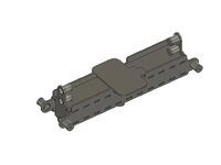
20 ton press jack base 1.jpg

The tubes are 1.25 OD DOM with 1.030" ID. A 1" diameter rod of UHMW will set in them and the cap will be tapped with a 3/8"-16 threads. A bolt and jamb nut will be adjusted to push the rod forward and locked to take up all play. The jack plate is sized for the HF air over hydraulic bottle jack.

20 ton press jack base 2.jpg

The center press rod is 1.5" 4140 5" long. 1/2" diameter counterbore and size tapped 1/4-20" set screw so interchangeable noses can be used. A tab is tack welded to the rod and retained to the cross member with two 3/8" bolts so it can be replaced if need be, but it pushes directly against the jack plate.

Every thing is laser cut 1/4" steel with tab and slot welds to assemble.
 
To avoid these ads, REGISTER NOW!
OP
F

Firebrick43

Well-known member
Joined
May 12, 2015
Messages
14,183
Location
West central Indiana
Decided last night before falling asleep that the UHMW tubes don't need to be 1.5" long, adjusted them to 7/8"

20 ton press jack base 3.png

Also shortened the ram end. Since it wont ever push directly on the part in this configuration, i can make longer or even different length ends to suite.

20 ton press jack base 4.png

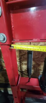
Does anyone have the return spring spacing on the newer gray HF 20 ton press? I forgot to take that measurement before I left on vacation and I sort of want to get the cut files to sendcutsend as soon as I can.
 

Jswain

Well-known member
Joined
Apr 26, 2013
Messages
2,465
Location
Calgary, AB
No help as I only have a 12t, but nice design. I like the setup for taking the slack with the UHMW.
 

RoninB4

Well-known member
Joined
Jul 22, 2020
Messages
3,615
Location
Under My House
Decided last night before falling asleep that the UHMW tubes don't need to be 1.5" long, adjusted them to 7/8"
-No info, sorry but asking what CAD program you're using? Looks like SolidWorks, that's what I have here at home. My 12T press from Horrible Freight has been waiting for me to make similar upgrades so it's not a "variable position" press.
 
OP
F

Firebrick43

Well-known member
Joined
May 12, 2015
Messages
14,183
Location
West central Indiana
No help as I only have a 12t, but nice design. I like the setup for taking the slack with the UHMW.
My 12T press from Horrible Freight has been waiting for me to make similar upgrades so it's not a "variable position" press.
I wonder how similar in dimensions the 12 ton is? If you take some pictures of the 12 ton jack cross member and vertical C channel with a tape measure in the pic I can see? There is a possibility that just a different top/bottom plate could be used with the existing side plates and end plates?
 

Sumboodie

Well-known member
Joined
Mar 20, 2021
Messages
10,737
Location
AK
How long does it take to computer draw that?

I have a 40 ton, it's ok, but non moveable cylinder
 
OP
F

Firebrick43

Well-known member
Joined
May 12, 2015
Messages
14,183
Location
West central Indiana
Might as well build a whole press!
😝
I thought considered it, but this is still much cheaper than a whole press as I couldn't buy the C Channel for what HF sold the whole press for.

The parts are precision cut and are self jigging. Drilling all the holes for the table pins in the length of channel accurately didn't appeal to me.
 
Last edited:
OP
F

Firebrick43

Well-known member
Joined
May 12, 2015
Messages
14,183
Location
West central Indiana
How long does it take to computer draw that?

I have a 40 ton, it's ok, but non moveable cylinder
The computer doesn't actually draw it, that is still me. But I have maybe 5 hours in it, an hour is fixing small mistakes and issues that the laser cutter checking program finds.

It saves a lot of time if the parts are mostly symmetrical, especially the tab and slots. You can draw 1/4 of the part and then mirror it horizontally/vertically.

The side plate I drew a slot and copied it several times to have the upper left corner of them done. Then mirrored it vertically. I then drew half of the profile. And then mirrored the whole shebang horizontally.

The 10 tubes with caps need drawn once then can be copied/rotated/moved into place quickly. When I made the change to the length of the tube if you do it in the correct place on the timeline, all 10 of them are updated at the same time.
 

RoninB4

Well-known member
Joined
Jul 22, 2020
Messages
3,615
Location
Under My House
I wonder how similar in dimensions the 12 ton is? If you take some pictures of the 12 ton jack cross member and vertical C channel with a tape measure in the pic I can see? There is a possibility that just a different top/bottom plate could be used with the existing side plates and end plates?
-Post a photo of the area you want with some arrows in photoshop (indicating what dimensions) and I'll take a photo today. Tell/show me what would help you.
 

RoninB4

Well-known member
Joined
Jul 22, 2020
Messages
3,615
Location
Under My House
I wonder how similar in dimensions the 12 ton is? If you take some pictures of the 12 ton jack cross member and vertical C channel with a tape measure in the pic I can see? There is a possibility that just a different top/bottom plate could be used with the existing side plates and end plates?
-PM sent with dimensions. Please excuse the crude photo editing, were you a paying customer I'd fire up the CAD program and make proper drawings. Hope it helped.
 

Jswain

Well-known member
Joined
Apr 26, 2013
Messages
2,465
Location
Calgary, AB
I wonder how similar in dimensions the 12 ton is? If you take some pictures of the 12 ton jack cross member and vertical C channel with a tape measure in the pic I can see? There is a possibility that just a different top/bottom plate could be used with the existing side plates and end plates?

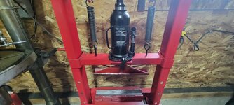
Hard to get a pic with the tape but here is a 12t pictured
 

Attachments

  • 20240828_131728.jpg
    20240828_131728.jpg
    335 KB · Views: 43
  • 20240828_131646.jpg
    20240828_131646.jpg
    384.1 KB · Views: 45
  • 20240828_131606.jpg
    20240828_131606.jpg
    488.8 KB · Views: 45
  • 20240828_131543.jpg
    20240828_131543.jpg
    520.2 KB · Views: 51
OP
F

Firebrick43

Well-known member
Joined
May 12, 2015
Messages
14,183
Location
West central Indiana
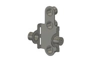
What do some of you think about this plate that is bent in a vise and welded on the seam? One would cut off the original ends of the jack crossmember and weld it on.

12 ton press stabilizer bracket 1.jpg
12 ton press stabilizer bracket 2.jpg
12 ton press stabilizer bracket 3.jpg
 

charbar

Well-known member
Joined
Feb 6, 2021
Messages
1,997
Location
Midwest
This is cool. I don't know how I'm just seeing this thread. I have the press you are working with so I can take some measurements if you still need anything.

My problem with just replacing the ends on the original part is that the pressing shaft on mine is welded and cut so crooked that it is basically impossible to use it for pressing on anything straight. I've contemplated taking it to my machine shop and having him machine it parallel with the plate the jack sits on, but it would still be a POS part :lol:

I would be VERY interested in buying a copy of your final file that you send to SendCutSend if you were ever interested in sharing your design. This looks like an great upgrade for these presses.
 

RoninB4

Well-known member
Joined
Jul 22, 2020
Messages
3,615
Location
Under My House
What do some of you think about this plate that is bent in a vise and welded on the seam? One would cut off the original ends of the jack crossmember and weld it on.
-For those of us (me anyway) that are concept challenged (no imagination) could you show a screen shot image of it on the press? You did a nice job modeling in CAD so would it take much more to model the press and slap your upgrade on it as an assembly model? Don't know if Fusion 360 works that way. Shouldn't take more than 20-30 minutes to do a quick-n-dirty modeling of that area of the press. Those of us playing along at home without the capacity for abstract thinking would be grateful.
 

david3921

Well-known member
Joined
Apr 22, 2014
Messages
442
Location
Wyoming, Michigan
-For those of us (me anyway) that are concept challenged (no imagination) could you show a screen shot image of it on the press? You did a nice job modeling in CAD so would it take much more to model the press and slap your upgrade on it as an assembly model? Don't know if Fusion 360 works that way. Shouldn't take more than 20-30 minutes to do a quick-n-dirty modeling of that area of the press. Those of us playing along at home without the capacity for abstract thinking would be grateful.

I too would to see it laid out. Your model doesn't show the '1" diameter rod of UHMW' for the adjustments which might be confusing to some. I like the design (I have this press) but question why there are two sets of tubes for adjustments on each side above the cross member rather than one set like below it.
 
OP
F

Firebrick43

Well-known member
Joined
May 12, 2015
Messages
14,183
Location
West central Indiana
-For those of us (me anyway) that are concept challenged (no imagination) could you show a screen shot image of it on the press? You did a nice job modeling in CAD so would it take much more to model the press and slap your upgrade on it as an assembly model? Don't know if Fusion 360 works that way. Shouldn't take more than 20-30 minutes to do a quick-n-dirty modeling of that area of the press. Those of us playing along at home without the capacity for abstract thinking would be grateful.
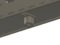
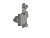
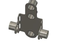
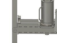
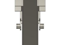
20 ton press jack base v4.1.jpg20 ton press jack base v4.2.jpg20 ton press jack base v4.3.jpg20 ton press jack base v4.4.jpg

The jack is not the correct model but it gives an idea. The C channel is simplified (no taper to the interior) but the outside dimensions are correct. Pictures 3 and 4 show the 0.25 gap to the C Channel. I am not going to insert the UHMW rods in the model but they would be in the cups and are adjusted to take up the gap without binding. the 0.25" on each side leaves a full 0.50" total adjustment possible.
 
OP
F

Firebrick43

Well-known member
Joined
May 12, 2015
Messages
14,183
Location
West central Indiana
I too would to see it laid out. Your model doesn't show the '1" diameter rod of UHMW' for the adjustments which might be confusing to some. I like the design (I have this press) but question why there are two sets of tubes for adjustments on each side above the cross member rather than one set like below it.
The more area there is and the further apart they are on the inside of the rails the more resistant to cocking it will be.

I put only one below the crossmember as if there was more it could run into issues hitting items to be pressed or attachments such as the SWAG off road finger brake.

Above the cross member there is more room as the jack cylinder completely collapsed leaves plenty of room for a second one. Even more could be added but its probably past a point of diminishing returns.
 

Lwel9226

Well-known member
Joined
Jun 7, 2014
Messages
764
Location
So Oregon
I did something mechanically very similar to yours.... But mine is not nearly as pretty as yours :D....
I used 1/4 in. UHMW flat stock at the wear points..... A big improvement in the press....

LynnW
 
To avoid these ads, REGISTER NOW!

RoninB4

Well-known member
Joined
Jul 22, 2020
Messages
3,615
Location
Under My House
First thought before the coffee kicks in.....nice modeling, knew you could do it. Thought the UHMW rollers would be on the inside of the vertical rails. I'm not awake enough for analysis, more later....
 

Jswain

Well-known member
Joined
Apr 26, 2013
Messages
2,465
Location
Calgary, AB
First thought before the coffee kicks in.....nice modeling, knew you could do it. Thought the UHMW rollers would be on the inside of the vertical rails. I'm not awake enough for analysis, more later....
They aren't rollers. Those are tubes he would weld on & thread the end cap so that when he cuts ~1" lengths of 1" diameter UHMW rods they will sit inside the tubes and be pushed out with an adjustment bolt.
 

david3921

Well-known member
Joined
Apr 22, 2014
Messages
442
Location
Wyoming, Michigan
They aren't rollers. Those are tubes he would weld on & thread the end cap so that when he cuts ~1" lengths of 1" diameter UHMW rods they will sit inside the tubes and be pushed out with an adjustment bolt.

Wouldn't some type of roller be better though? Wouldn't the UHMW wear the paint/powder coat away with up/down movement?
 

Jswain

Well-known member
Joined
Apr 26, 2013
Messages
2,465
Location
Calgary, AB
Wouldn't some type of roller be better though? Wouldn't the UHMW wear the paint/powder coat away with up/down movement?
I would think it would take a LONG time for UHMW to wear away the powder coating. You just tighten it up enough to either barely touch or leave a slight amount of movement.

Sure a roller would be "better" but overkill as well. I just shoved some pieces of cut 1/8" cutting board in mine and glued it on. Most of them have fell off by now but I don't use the press enough that it bothers me. If I was getting pieces laser cut with the intent of using the press to make production parts or such then I could see wanting to make the cross bar better.
 

david3921

Well-known member
Joined
Apr 22, 2014
Messages
442
Location
Wyoming, Michigan
I would think it would take a LONG time for UHMW to wear away the powder coating. You just tighten it up enough to either barely touch or leave a slight amount of movement.

Sure a roller would be "better" but overkill as well. I just shoved some pieces of cut 1/8" cutting board in mine and glued it on. Most of them have fell off by now but I don't use the press enough that it bothers me. If I was getting pieces laser cut with the intent of using the press to make production parts or such then I could see wanting to make the cross bar better.

Thanks for the info on UHMW. I don't use my press a whole lot either but I do notice the cross bar flex when I do.
 

alfadan

Well-known member
Joined
Mar 9, 2007
Messages
2,117
Location
Augusta, ks
If you’re talking to me they are Hot rolled plate that appears to be plasma cut to shape. The could be flame cut as well if it was well tuned?

They've all come with torch/flame cut plates for a LONG time. Mine is 10+ years old and they are flame cut steel
I knew they been for awhile, just didn't know when. I guess I thought someone said they were forged, but that would be silly.

My older orange press came with cast. I bought some plate ones last year for a good deal.
 

KwikFab

Well-known member
Joined
Jul 27, 2024
Messages
1,216
Location
Central Valley, CA
Yes the jack plate shown is drawn to the base of a HF bottle jack.

I wasn’t going to draw the jack so I downloaded the CAD drawing from McMaster car but it’s just a manual one

Gotcha.

The base width on say, the Torin is 5 7/32" (round up to 5 1/4") and 8 29/32" long (round up to 8 15/16").

20240830_115148.jpg

Used to have the HF air over hydraulic but got rid of it.

Just pointing it out because I'd never subject myself or anyone to using the manual jack.
 
OP
F

Firebrick43

Well-known member
Joined
May 12, 2015
Messages
14,183
Location
West central Indiana
Gotcha.

The base width on say, the Torin is 5 7/32" (round up to 5 1/4") and 8 29/32" long (round up to 8 15/16").

20240830_115148.jpg

Used to have the HF air over hydraulic but got rid of it.

Just pointing it out because I'd never subject myself or anyone to using the manual jack.
That just slightly bigger than the HF air over hydraulic Jack.

Mine is 5 1/8” x 8 1/2”

What did you find objectionable about the HF one compared to the Torin?

I haven’t used the A over H one yet.
 

KwikFab

Well-known member
Joined
Jul 27, 2024
Messages
1,216
Location
Central Valley, CA
That just slightly bigger than the HF air over hydraulic Jack.

Mine is 5 1/8” x 8 1/2”

What did you find objectionable about the HF one compared to the Torin?

I haven’t used the A over H one yet.

Torin was only $93 with free shipping

Being Chinese-made it's fair to say they're both the same (mostly)

I've never used a manual jack on a press; it's far more efficient using air over hydraulic not to mention safer since you can use both hands for handling reasons
 

RoninB4

Well-known member
Joined
Jul 22, 2020
Messages
3,615
Location
Under My House
Just pointing it out because I'd never subject myself or anyone to using the manual jack.

-Never used an A over H and don't know why I'd want one. I've used several of the Dake 150H manual presses and found them to be quite adequate for what I was doing. For handling/alignment I'd rather use a screw adjustment on the end of the ram that I can control. If the A over H down-feed is strictly power driven ( I wouldn't know) then some of the minute movements capability is lost. That's just an opinion based upon how I use the press where alignment is everything.
 

GeoBruin

Well-known member
Joined
May 5, 2018
Messages
3,750
-Never used an A over H and don't know why I'd want one. I've used several of the Dake 150H manual presses and found them to be quite adequate for what I was doing. For handling/alignment I'd rather use a screw adjustment on the end of the ram that I can control. If the A over H down-feed is strictly power driven ( I wouldn't know) then some of the minute movements capability is lost. That's just an opinion based upon how I use the press where alignment is everything.
Air over hydraulic jacks typically allow manual operation as well. It's nice to run the jack down to the part, engage it manually to check alignment etc., then do the bend on air but stop shy and finish up manually.

Definitely not all or nothing.
 

charbar

Well-known member
Joined
Feb 6, 2021
Messages
1,997
Location
Midwest
Air over hydraulic jacks typically allow manual operation as well. It's nice to run the jack down to the part, engage it manually to check alignment etc., then do the bend on air but stop shy and finish up manually.

Definitely not all or nothing.


I also use the air part when I'm doing sketchy stuff and tell myself I'm safe if I stand beside the press, close my eyes and run the air that way :lol:
 

charbar

Well-known member
Joined
Feb 6, 2021
Messages
1,997
Location
Midwest
Don't forget to put your hand over your family jewels!


Well that's just second nature, almost like breathing. Actually now that I think about it I'm pretty sure I hold my breath when I do things like that.......so I think I just proved that protecting your nuts is more important than breathing!
 
To avoid these ads, REGISTER NOW!
Top Bottom